
STM32 Baremetal Examples
“Bare Metal” STM32 Programming (Part 12): Using Quad-SPI Flash Memory
If I had to guess what the world’s most popular footprint for low-density memory chips was, I would probably be wrong. But I’ll bet that the humble 8-pin SOIC / DIP / DFN formats would be near the top. You’ve probably used these before; most ESP8266 and ESP32 modules have one under their little metal shield, and motherboards for computers / cars / synthesizers / etc. often use them for storing UEFI / BIOS / firmware configurations and suchlike.

Pin assignments for a generic Flash module (Winbond W25Q series)
You can get RAM, Flash, EEPROM, and even FRAM memory in these common 8-pin packages. They usually use a SPI interface for communication, with a couple of extra pins for functions like write protection or suspending an ongoing transaction. But if you look in the image above, you’ll see that the /WP “Write Protect” and /HOLD or /RESET wires are also marked as IO2 and IO3. That’s because many 8-pin Flash chips also support a “Quad-SPI” interface, which is very similar to a bidirectional “3-wire” SPI interface, except that it has four I/O wires instead of one.
Some STM32 chips include a QSPI peripheral to interface with these kinds of Flash memory chips. You can use it to manually configure / erase / program the Flash chip, and once it’s initialized, you can also map the external Flash as read-only memory in the STM32’s internal memory space. The peripheral supports prefetching, caching, executing code, and it can even access two QSPI Flash chips in parallel, using 8 data lines in total to transfer a full byte of data every clock cycle.
To learn about the QSPI peripheral, I used the same STM32F723E Discovery Kit from my last post about external memories. In addition to its external RAM and display, this board includes one 64MB QSPI Flash chip connected to the QSPI peripheral. In this post, we’ll learn how to configure the Flash chip for quad I/O access, erase a sector, and write some test values. Then we’ll set the QSPI peripheral to its read-only “memory-mapped” mode, and read those test values by accessing the chip’s internal memory space starting at 0x90000000. If you don’t like copy/pasting, you can find an example project with this code on GitHub.
It is a little bit annoying that you can’t write to the Flash chip in memory-mapped mode, but this peripheral still presents a simple way to quickly read from external Flash using only six I/O pins. And writing to Flash memory has some unique limitations anyways, which is why it is often used to store data which an application rarely needs to modify, like firmware or audio/visual resources. So if you want to learn how to use Quad-SPI Flash memories with an STM32, read on!
“Bare Metal” STM32 Programming (Part 11): Using External Memories
Modern microcontrollers are amazing. They are much faster and cheaper than the sort of processors that powered “real” computers a few decades ago, and they’re also very power-efficient. But software complexity has also grown over time, and as we humans often say about ourselves as we age, it has grown in the wrong direction. Developers have gotten used to having enormous reserves of memory to draw from, so unless an application or library was specifically written for embedded platforms, it probably won’t be able to run with the scant kilobytes of RAM which are included in your average microcontroller.
Fortunately, most vendors include peripherals for accessing external memory when it is needed, and the STM32’s “Flexible Memory Controller” is surprisingly easy to use. Unfortunately, it is not easy to design a custom PCB with parallel memory modules. The interfaces use a lot of signals which are susceptible to electromagnetic noise, so it is important to ensure that all of the traces have the same length and impedance. This is especially hard on hobbyists, because 2-layer boards are not appropriate for these sorts of designs and KiCAD does not support length-matching for more than two traces yet.
So the target hardware for this tutorial will be a $40 STM32F723E Discovery Kit. It is a bit more expensive than the minimal “Nucleo” boards, but it includes 512KB of external RAM and a 240×240-pixel TFT display; we’ll learn how to drive both of those from the FMC peripheral in this post. It also includes 64MB of memory-mapped QSPI Flash memory, which I’ll talk about in a future post.

We’ll use the external RAM to store a framebuffer, which will be sent to the display using DMA.
This evaluation board uses BGA parts, which are almost impossible to solder without special equipment. But it provides an easy and affordable way to learn about writing software for these peripherals. When you are ready to use external memories in homemade designs, you can use QFP STM32s with at least 144 pins, TSSOP memory chips, and a 4-layer PCB.
Festive Cross-Platform Holiday Lights
Across the globe, people seem to enjoy decorating their homes, communities, and outdoor spaces with lights and ornaments during the winter holidays. Maybe it helps with the depressingly early sunsets for those of us who don’t live near the equator. Anyways, I thought it’d be fun to make some ornaments with multi-color addressable LEDs last year, and I figured I’d write about what worked and what didn’t.
I didn’t have many microcontrollers at the time because I was visiting family for the holidays, so I ended up coding the lighting patterns for a cheap little STM32F103 “black pill” board which was in the bottom of my backpack. And it’s a convenient coincidence that I just started learning about the very similar GD32VF103 chips with their fancy RISC-V CPUs and nearly-identical peripheral layout, so this also seems like a good opportunity to write about how to cross-compile the same code for two different CPU architectures.

Pretty holiday stars! “Frosted white” acrylic sheets aren’t the best way to diffuse light, but they are cheap and easy to work with.
This was a fun and festive project, and it might not be a bad way to introduce people to embedded development since there are so many ways to drive these ubiquitous “NeoPixel” LEDs. Sorry that this post is a little bit late for the winter holidays – I’ve been traveling for the past few months – but maybe it’ll get you thinking about next year 🙂
I’ll talk about how I assembled the stars and what I might do differently next time, then I’ll review how to light them up with an STM32F103, and how to adapt that code for a GD32VF103. But you could also use a MicroPython or Arduino board to set the LED colors if you don’t want to muck around with peripheral registers.
Designing a Simple GPS Handheld
I’ve written a little bit in the past about how to design a basic STM32 breakout board, and how to write simple software that runs on these kinds of microcontrollers. But let’s be honest: there’s still a bit of a gap between creating a small breakout board to blink an LED, and building hardware / software for a ‘real-world’ application. Personally, I would still want a couple of more experienced engineers to double-check any designs that I wanted to be reliable enough for other people to use, but building more complex applications is a great way to help yourself learn.
So in this post, I’m going to walk through the process of designing a small ‘gameboy’-style handheld with a GPS receiver and microSD card slot, for exploring the outdoors instead of video games. Don’t get me wrong, you could still write games to run on this if you wanted to, and that would be fun, but everyone and their dog has made a Cortex-M-based handheld game console by now; there are plenty of better guides for that, and many of those authors put a lot more time into their designs and firmware than I ever did.
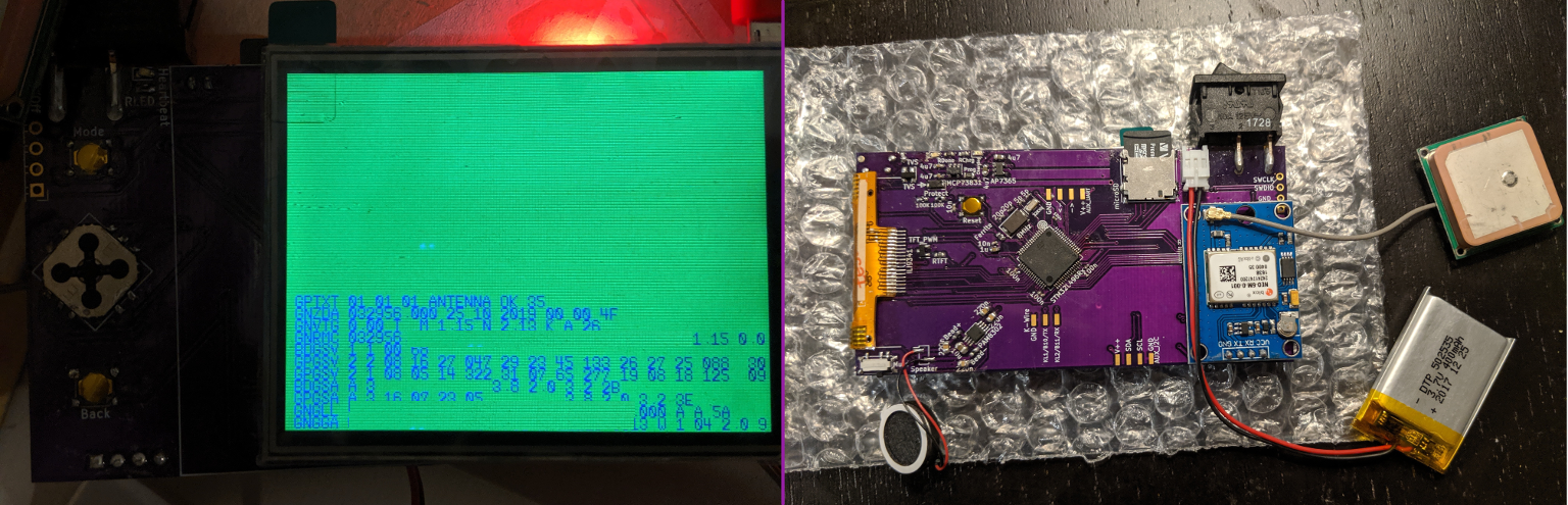
Assembled GPS Doohicky. I left too much room between the ribbon connector footprint and the edge of the board on this first revision, so the display couldn’t fold over quite right. Oh well, you live and learn.
The board design isn’t too complicated, but there are several different parts and it gets easier to make small-but-important mistakes as a design gets larger. It mostly uses peripherals that I’ve talked about previously, but there are a couple of new ones too. The display will be driven over SPI, the speaker uses a DAC, the GPS receiver talks over UART, the battery and light levels will be read using an ADC, and the buttons will be listened to using interrupts. But I haven’t written about the USB or SD card (“MMC”) peripherals, and those will need to go in a future post since I haven’t actually worked them out myself yet. Note that SD cards can technically use either SPI or SD/MMC to communicate, but the microcontroller that I picked has a dedicated SD/MMC peripheral, and I wanted to learn about it.
Anyways, if that sounds interesting, read on and let’s get started!
Reading Battery Voltage with the STM32’s ADC
If you choose to pursue embedded development beyond the occasional toy project, it probably won’t take long before you want to design something which runs off of battery power. Many types of devices would not be useful if they had to be plugged into a wall outlet all the time, and power efficiency is one of the biggest advantages that microcontrollers still have over application processors like the one in a Raspberry Pi.
When you do move an application to battery power, you’ll quickly discover that it is very important for your device to be able to A) charge its battery and B) alert you when its battery is running low. Not knowing whether something has hours or seconds of life left can be really annoying, and trying to use a nearly-dead battery can cause strange behavior, especially if the battery’s power drops off slowly as it dies. Most lithium-based batteries also last longer if you avoid fully discharging them – there’s some good information about lithium battery aging in this article.
So in this post, I’m going to go over a very basic circuit to power an STM32 board off of a single lithium-ion battery and monitor its state of charge. I will also talk briefly about how to add a simple battery charger to your design, but you should always independently verify any circuitry which interacts with lithium batteries! This circuit seems to work to the best of my knowledge, but don’t take my word for it; it’s very important to double- and triple-check your li-po battery circuits, because they can easily become serious fire hazards if they are handled improperly. It’s also good practice to avoid leaving lithium-ion batteries unattended while they are charging, and you should try to get batteries with built-in protection circuitry to help mitigate bad situations like over-current, under-voltage, etc.
So with those brief and not comprehensive safety warnings out of the way, let’s get started! I’ll use an STM32L4 chip for this example, but the ADC peripheral doesn’t seem to change much across STM32s. And here is a GitHub repository containing design files for a simple board which demonstrates the concepts described in this post.
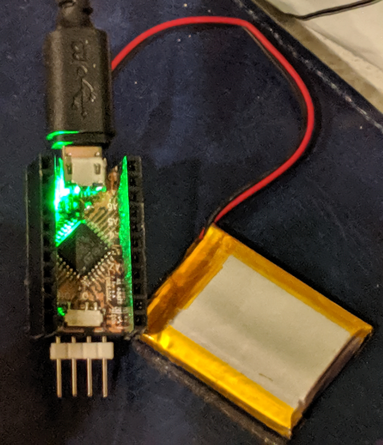
Hooray, it’s fully charged!
New 8-pin ARM Core: the STM32G031J6
It has been about nine months since ST released their new STM32G0 line of microcontrollers to ordinary people like us, and recently they released some new chips in the same linup. It sounds like ST wants this new line of chips to compete with smaller 8-bit micros such as Microchip’s venerable AVR cores, and for that market, their first round of STM32G071xB chips might be too expensive and/or too difficult to assemble on circuit boards with low dimensional tolerances.
Previously, your best bet for an STM32 to run a low-cost / low-complexity application was probably one of the cheaper STM32F0 or STM32L0 chips, which are offered in 16- and 20-pin TSSOP packages with pins spaced 0.65mm apart. They work great, but they can be difficult to use for rapid prototyping. It’s hard to mill or etch your own circuit board with tight enough tolerances, and it’s not very easy to solder the chips by hand. Plus, the aging STM32F031F6 still costs $0.80 each at quantities of more than 10,000 or so, and that’s pretty expensive for the ultra-cheap microcontroller market.
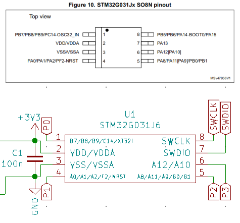
Pinout and minimal circuit for an STM32G031J6 – you only really need one capacitor if you have a stable 3.3V source.
Enter the STM32G031J6: an STM32 chip which comes in a standard SOIC-8 package with 32KB Flash, 8KB RAM, a 64MHz speed limit, and a $0.60 bulk price tag (closer to $1.20-1.40 each if you’re only buying a few). That all compares favorably to small 8-pin AVR chips, and it looks like they might also use a bit less power at the same clock speeds. Power consumption is a tricky topic because it can vary a lot depending on things like how your application uses the chip’s peripherals or what voltage the chip runs off of. But the STM32G0 series claims to use less than 100uA/MHz, and that is significantly less than the 300uA/MHz indicated in the ATTiny datasheets. Also, these are 32-bit chips, so they have a larger address space and they can process more data per instruction than an 8-bit chip can.
Considering how easy STM32 chips are to work with, it seems like a no-brainer, right? So let’s see how easy it is to get set up with one of these chips and blink an LED.
Hello, Rust: Blinking LEDs in a New Language
Rust is a fairly new language that has gotten to be very popular in recent years. And as the language matures, it has started to support a wider set of features, including compilation and linking for bare-metal targets. There is an excellent “Embedded Rust” ebook being written which covers the concepts that I’ll talk about here, but it’s still in-progress and there aren’t many turn-key code examples after the first couple of chapters.
The Rust language is less than 10 years old and still evolving, so some features which might change in the future are only available on the nightly branch at the time of writing; this post is written for rustc version 1.36. And the language’s documentation is very good, but it can also be a little bit scattered in these early days. For example, after I had written most of this post I found a more comprehensive “Discovery ebook” which covers hardware examples for an STM32F3 “Discovery Kit” board. That looks like a terrific resource if you want to learn how to use the bare-metal Rust libraries from someone who actually knows what they’re talking about.
As a new Rustacean, I’ll admit that the syntax feels little bit frustrating at times. But that’s normal when you learn a new language, and Rust is definitely growing on me as I learn more about its aspirations for embedded development. Cargo looks promising for distributing things like register definitions, HALs, and BSPs. And there’s an automated svd2rust utility for generating your own register access libraries from vendor-supplied SVD files, which is useful in a language that hasn’t had time to build up an extensive set of well-proven libraries. So in this post I’ll talk about how to generate a “Peripheral Access Crate” for a simple STM32L031K6 chip, and how to use that crate to blink an LED.

It’s kind of fun when languages have mascots, especially when they’re CC0-licensed.
The target hardware will be an STM32L031K6 Nucleo-32 board, but this should work with any STM32L0x1 chip. I also tried the same process with an STM32F042 board and the STM32F0x2 SVD file, which worked fine. It’s amazing how easy it is to get started with a new chip compared to C, although you do still need to read the reference manuals to figure out which registers and bits you need to modify. This post will assume that you know a little bit about how to use Rust, but only the very basics – I’m still new to the language and I don’t think I would do a good job of explaining anything. The free Rust ebook is an excellent introduction, if you need a quick introduction.
Keeping Up With the Moorses: Learning to Use STM32G0 Chips
Microcontrollers are just like any other kind of semiconductor product. As manufacturers learn from customer feedback and fabrication processes continue to advance, the products get better. One of the most visible metrics for gauging a chip’s general performance – and the basis of Moore’s Law – is how large each transistor is. Usually this is measured in nanometers, and as we enter 2019 the newest chips being made by companies like Samsung and Intel are optimistically billed as 7nm.
The venerable and popular STM32F1 series is more than a decade old now, and it is produced using a 130nm process. But ST’s newer lines of chips like the STM32L4 use a smaller 90nm process. Smaller transistors usually mean that chips can run at lower voltages, be more power-efficient, and run at faster clock speeds. So when ST moved to this smaller process, they introduced two types of new chips: faster ‘mainline’ chips like the F4 and F7 lines which run at about 100-250MHz, and more efficient ‘low-power’ chips like the L0 and L4 lines which have a variety of ‘sleep’ modes and can comfortably run off of 1.8V. They also have an H7 line which uses an even smaller 40nm process and can run at 400MHz.
Now as 2018 fades into history, it looks like ST has decided that it’s time for a fresh line of ‘value-line’ chips, and we can order a shiny new STM32G0 from retailers like Digikey. At the time of writing there aren’t too many options, but it looks like they’re hoping to branch out and there are even some 8-pin variants on the table. I could be misreading things, but these look like a mix between the F0 and L0 lines, with lower power consumption than F0 chips and better performance than the L0 chips. The STM32G071GB that I made a test board with has 128KB of Flash, 36KB of RAM, and a nice set of communication peripherals.
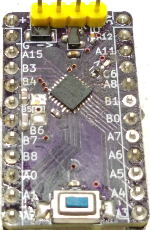
Simple STM32G0 breakout board
So what’s the catch? Well, this is still a fairly new chip, so “Just Google It” may not be an effective problem-solving tool. And it looks like ST made a few changes in this new iteration of chips to provide more GPIO pins in smaller packages, so the hardware design will look similar but slightly different from previous STM32 lines. Finally, with a new chip comes new challenges in getting an open-source programming and debugging toolchain working. So with all of that said, let’s learn how to migrate!
“Bare Metal” STM32 Programming (Part 8): Learn to Debug Timing Issues with Neopixels
I haven’t written about STM32 chips in a little while, but I have been learning how to make fun displays and signage using colorful LEDs, specifically the WS2812B and SK6812 ‘Neopixels’. I talked about the single-wire communication standard that these LEDs use in a post about running them from an FPGA, and I mentioned there that it is a bit more difficult for microcontrollers to run the communication standard. If you don’t believe me, take a look at what the poor folks at Adafruit needed to do to get it working on a 16MHz AVR core. Yikes!
When you send colors, the 1 bits are fairly easy to encode but the 0 bits require that you reliably hold a pin high for just 250-400 nanoseconds. Too short and the LED will think that your 0 bit was a blip of noise, too long and it will think that your 0 is a 1. Using timer peripherals is a reasonable solution, but it requires a faster clock than 16MHz and we won’t be able to use interrupts because it takes about 20-30 clock cycles for the STM32 to jump to an interrupt handler. At 72MHz it takes my code about 300-400 nanoseconds to get to an interrupt handler, and that’s just not fast enough.
There are ways to make it faster, but this is also a good example of how difficult it can be to calculate how long your C code will take to execute ahead of time. Between compiler optimizations and hardware realities like Flash wait-states and pushing/popping functions, the easiest way to tell how long your code takes to run is often to simply run it and check.
Pulseview diagram of ‘101’ in Neopixel. I can’t be sure, but I think the ‘0’ pulse might be about 375 nanoseconds long.
Which brings us to the topic of this tutorial – we are going to write a simple program which uses an STM32 timer peripheral to draw colors to ‘Neopixel’ LEDs. Along the way, we will debug the program’s timing using Sigrok and Pulseview with an affordable 8-channel digital logic analyzer. These are available for $10-20 from most online retailers; try Sparkfun, or Amazon/eBay/Aliexpress/etc. I don’t know why Adafruit doesn’t sell these; maybe they don’t want to carry cheap generics in the same category as Salae analyzers. Anyways, go ahead and install Pulseview, brush up a bit on STM32 timers if you need to, and let’s get started!