
Up until this point, I’ve only written about embedded applications which get loaded into a device’s non-volatile memory. That’s how most “normal” programs work, but it’s not the only way to run code on a microcontroller. There are plenty of situations where you might want to run a one-off program on a device before resetting it to its previous state. Maybe your microcontroller has a large firmware image that takes a long time to erase and restore, or maybe you want to perform a one-time data transfer between your laptop and a device which is connected to your microcontroller.
When you encounter those sorts of situations, you can write a program to run from your microcontroller’s RAM instead of its Flash memory. There are a few extra steps to be aware of, and the process of loading and running the program is a bit different, but you won’t need to change much in the application’s C code.
In this post, I’ll try to demonstrate how and why to run code from RAM with a couple of examples. First we’ll write a minimal RAM program to blink an LED. Then, once we know how to load code into RAM and run it, we’ll write an ephemeral program which can send a file from our computer to a QSPI Flash chip connected to the microcontroller.
I’ll also talk a bit about the “Tightly-Coupled Memory” segments available on ARM Cortex-M7 CPUs. Those are small areas of RAM which are good for storing critical realtime code thanks to their fast and deterministic access speed.
The target hardware will be the same STM32F723 Discovery Kit board that I used in my last two tutorials about external memories, since it is pretty affordable and it includes a QSPI Flash chip.
Creating a “Hello World” RAM Program
Writing a program to run from RAM is different from writing one to run from Flash memory in a few important ways:
- You need to set up an interrupt vector table in RAM, and tell the chip where that new vector table is.
- You need to create a linker script which puts all of the program sections in RAM.
- Your
Makefilecan be a bit simpler. - Loading and running the program works differently.
Let’s look at each of those steps individually.
Relocating the Vector Table
Remember from the first few entries in this series of posts, the vector table is an area of memory which tells the microcontroller where various interrupt handler functions are located. Setting up a vector table in RAM is easy; you can simply define an array of uint32_ts with the required number of entries.
In the case of an STM32F723IE, we have 120 vector table entries. You can look at the “Interrupt and Exception Vectors” table in the reference manual’s NVIC chapter to see how many interrupts there are. Here, the last entry (SDMMC2) has an offset of 0x1DC = 476 bytes = 119 words, and they are zero-indexed. So all you have to do is define something like this in a handy header file (or at the top of main.c in a minimal example like this):
__attribute__((aligned(0x200))) volatile uint32_t irqs[ 120 ];
The aligned attribute tells the GCC toolchain that wherever it puts this array in memory, it should be aligned to a boundary of at least 0x200 bytes. Cortex-M CPUs require the vector table to be aligned to a boundary width of the lowest power of 2 that will fit the entire vector table. We have 120 interrupt slots occupying 480 bytes, so we align the vector table to a 512-byte boundary (0x200 = 512).
Before you enable any interrupts, you’ll need to tell the CPU where its new vector table is located. You can do this by setting the SCB->VTOR register to the array’s memory address, probably near the start of your main method:
  // Relocate the vector table.
  SCB->VTOR      =  ( uint32_t )&irqs;
When you want to use an interrupt, you can set the appropriate index in the irqs array to the memory address of its interrupt handler function before you enable the interrupt. For example, to enable the SysTick interrupt in a RAM program, you could do something like this:
// SysTick interrupt handler: increment a 'systick' counter.
volatile uint32_t systick = 0;
void systick_handler( void ) {
  ++systick;
}

  // (Somewhere near the start of main()...)
  // Set an entry for the SysTick interupt.
  irqs[ SysTick_IRQn + 16 ] = ( uint32_t )systick_handler;
  // Setup the SysTick peripheral to trigger every 1000 cycles.
  SysTick_Config( 1000 );
  // (etc...)
The irqs array index has a 16-word offset because if you look in the stm32f723xx.h device header file, you’ll see that the first several listings in the IRQn_Type enum have negative position numbers. These interrupts are part of the ARM Cortex-M CPU, while the others are part of the wider STM32 system-on-chip. The reference manual says that the entry with position 0 (WWDG_IRQn) has an address offset of 0x40 = 64 bytes = 16 words. So if you want to set an interrupt handler with position N, you need to address entry N + 16 in the irqs array.
It’s also a good idea to set up a default interrupt handler for important Cortex-M interrupts like BusFault, UsageFault, etc. Since the irqs array will probably go in the .bss section, all of its entries will be set to zero when we memset that section of RAM at the start of our program. That means that if an interrupt which you haven’t configured gets triggered, it will jump to address 0x00000000, which will probably contain ITCM RAM or the vector table for whatever program is stored in non-volatile memory (unless you’ve changed the BOOT0 / BOOT1 signals from the usual 0 / 0).
So if you don’t set an interrupt handler for UsageFault_IRQn and your RAM program crashes, as best I can tell, the program will either “forget” your RAM program and go back to whatever is in its Flash memory, or run whatever is located at the start of the ITCM RAM bank. I haven’t experimented too much with this, but it’s better safe than sorry:
  // Set the "end of stack" address.
  irqs[ 0 ] = _estack;
  // Set the RAM program's reset handler location.
  irqs[ 1 ] = ( uint32_t )reset_handler;
  // Set an entry for non-maskable and fault interrupts.
  irqs[ NonMaskableInt_IRQn + 16 ] = ( uint32_t )error_handler;
  irqs[ BusFault_IRQn + 16 ] = ( uint32_t )error_handler;
  irqs[ UsageFault_IRQn + 16 ] = ( uint32_t )error_handler;
You can see that I also set the first two entries to the RAM program’s “end of stack” and reset handler addresses, for the sake of completeness. Next, we need to update the linker script so that our program doesn’t expect any data to be in Flash memory.
Modifying the Linker Script
The linker script doesn’t need many changes, compared to what you’d use with a normal GCC program built to run from a microcontroller’s Flash memory.
First, simply replace all of the occurrences of >FLASH with >RAM. That tells the linker to put memory sections containing read-only constants and program data into the RAM’s memory space.
Next, remove the vector table section entry, which I usually call something like .vector_table or .vtable. We’re defining the vector table as an array in the main program, so it will probably be placed in the .bss section. You can also remove the FLASH entry from the MEMORY definition.
You should end up with something like this for an STM32F723IE:
[ STM32F723IE.ld: ]
/* Label for the program's entry point */
ENTRY(reset_handler)

/* Starting stack address */
_estack = 0x2003C000;

MEMORY
{
    RAM2      ( rxw )   : ORIGIN = 0x2003C000, LENGTH = 16K
    RAM       ( rxw )   : ORIGIN = 0x20010000, LENGTH = 176K
    DTCMRAM   ( rxw )   : ORIGIN = 0x20000000, LENGTH = 64K
    ITCMRAM   ( rxw )   : ORIGIN = 0x00000000, LENGTH = 16K
}

INCLUDE "sections.ld"

[ sections.ld: ]
SECTIONS
{
  /* The 'text' section contains the main program code. */
  .text :
  {
    . = ALIGN(4);
    KEEP (*(.reset))
    *(.text)
    *(.text*)
    KEEP (*(.init))
    KEEP (*(.fini))
    KEEP (*(.eh_frame))
    . = ALIGN(4);
  } >RAM

  /* Sections required by the standard libraries. */
  .ARM.extab :
  {
    *(.ARM.extab* .gnu.linkonce.armextab.*)
  } >RAM
  .ARM :
  {
    *(.ARM.exidx*)
  } >RAM

  /* The 'rodata' section contains read-only data,
   * constants, strings, information that won't change. */
  .rodata :
  {
    . = ALIGN(4);
    *(.rodata)
    *(.rodata*)
    . = ALIGN(4);
  } >RAM

  /* The 'data' section is space set aside in RAM for
   * things like variables, which can change. */
  _sidata = .;
  .data : AT(_sidata)
  {
    . = ALIGN(4);
    /* Mark start/end locations for the 'data' section. */
    _sdata = .;
    *(.data)
    *(.data*)
    . = ALIGN(4);
    _edata = .;
  } >RAM

  /* The 'bss' section is similar to the 'data' section,
   * but its space is initialized to all 0s at the
   * start of the program. */
  .bss :
  {
    . = ALIGN(4);
    /* Also mark the start/end of the BSS section. */
    _sbss = .;
    __bss_start__ = _sbss;
    *(.bss)
    *(.bss*)
    *(COMMON)
    . = ALIGN(4);
    _ebss = .;
    __bss_end__ = _ebss;
  } >RAM
  /* Mark the end of statically-allocated RAM. */
  end = .;
  _end = end;
  __end = end;
}
I like to use a separate sections.ld file to store common memory sections, because that makes it easier to add support for different chips.
If you look at the MEMORY definition, you can see that this chip has four separate “banks” of RAM. There are two main banks, which act like normal RAM: one is 176KiB, the other is 16KiB. Then there are two very fast “Tightly-Coupled Memory” (TCM) banks which are part of the Cortex-M7 CPU: one is 64KiB and connected to the data bus, the other is 16KiB and connected to the instruction bus.
Tightly-Coupled Memory
Because the CPU has a dedicated bus for accessing each TCM RAM, these banks can be accessed quickly and deterministically, sort of like a cache. I haven’t tried using them for anything interesting yet, but it sounds like these memories are good for applications with hard real-time requirements because they give you guaranteed memory access timings. (Remember that normal RAM access can be delayed by things like DMA transfers using the same bus.)
If you’re using a chip with TCM RAM, there are a few ways that you can use them to speed up a general-purpose application. First, you can put your program’s stack in the DTCM bank by changing the _estack value in the linker script, and splitting the DTCMRAM section in half:
/* Label for the program's entry point */
ENTRY(reset_handler)

/* Starting stack address */
_estack = 0x20008000;

MEMORY
{
    FLASH     ( rx )    : ORIGIN = 0x08000000, LENGTH = 512K
    RAM2      ( rxw )   : ORIGIN = 0x2003C000, LENGTH = 16K
    RAM       ( rxw )   : ORIGIN = 0x20010000, LENGTH = 176K
    DTCMRAM_S ( rxw )   : ORIGIN = 0x20000000, LENGTH = 32K
    DTCMRAM_V ( rxw )   : ORIGIN = 0x20008000, LENGTH = 32K
    ITCMRAM   ( rxw )   : ORIGIN = 0x00000000, LENGTH = 16K
}

INCLUDE "sections.ld"
That will make the stack use the first half of the DTCM RAM bank, from 0x20000000 to 0x20008000. I also removed the .dynamic_allocations section, because we don’t need a “buffer” at the end of our RAM sections when the stack is located in a different memory bank. If our stack overflowed, it wouldn’t collide with our program data. Instead, it would try to access a memory address like 0x1FFFFFFE and crash.
You can also put the vector table in DTCM RAM to reduce interrupt latency a bit. In addition to removing the stack space buffer, the linker script’s sections.ld file will need updating to include sections for the DTCM and ITCM banks.
Both TCM sections can contain initialized data, like the main .data section. So we can use the same sort of AT(...) syntax to store that initialized data in the main program storage, while linking the program to refer to memory addresses in the TCM banks. Normally these _si[...] sections would go in Flash memory, but we’re running these programs from RAM:
SECTIONS
{
  /* The 'text' section contains the main program code. */
  .text :
  {
    . = ALIGN(4);
    KEEP (*(.reset))
    *(.text)
    *(.text*)
    KEEP (*(.init))
    KEEP (*(.fini))
    KEEP (*(.eh_frame))
    . = ALIGN(4);
  } >RAM

  /* Sections required by the standard libraries. */
  .ARM.extab :
  {
    *(.ARM.extab* .gnu.linkonce.armextab.*)
  } >RAM
  .ARM :
  {
    *(.ARM.exidx*)
  } >RAM

  /* The 'rodata' section contains read-only data,
   * constants, strings, information that won't change. */
  .rodata :
  {
    . = ALIGN(4);
    *(.rodata)
    *(.rodata*)
    . = ALIGN(4);
  } >RAM

  /* The 'data' section is space set aside in RAM for
   * things like variables, which can change. */
  _sidata = .;
  .data : AT(_sidata)
  {
    . = ALIGN(4);
    /* Mark start/end locations for the 'data' section. */
    _sdata = .;
    *(.data)
    *(.data*)
    . = ALIGN(4);
    _edata = .;
  } >RAM

  /* The 'bss' section is similar to the 'data' section,
   * but its space is initialized to all 0s at the
   * start of the program. */
  .bss :
  {
    . = ALIGN(4);
    /* Also mark the start/end of the BSS section. */
    _sbss = .;
    __bss_start__ = _sbss;
    *(.bss)
    *(.bss*)
    *(COMMON)
    . = ALIGN(4);
    _ebss = .;
    __bss_end__ = _ebss;
  } >RAM

  /* ITCM RAM region.
   * Tightly-coupled memory on the instruction bus. */
  _siitcm = .;
  .itcm : AT(_siitcm)
  {
    . = ALIGN(4);
    _sitcm = .;
    KEEP (*(.itcm_irqs))
    . = ALIGN(4);
    _eitcm = .;
  } >ITCMRAM
  . = _siitcm + ( _eitcm - _sitcm );

  /* DTCM RAM region.
   * Tightly-coupled memory on the data bus. */
  _sidtcm = .;
  .dtcm : AT(_sidtcm)
  {
    . = ALIGN(4);
    _sdtcm = .;
    KEEP (*(.dtcm_vars))
    . = ALIGN(4);
    _edtcm = .;
  } >DTCMRAM_V
  . = _sidtcm + ( _edtcm - _sdtcm );

  /* Mark the end of statically-allocated RAM. */
  end = .;
  _end = end;
  __end = end;
}
Unlike with the .data section, which is preceded by the non-volatile .rodata section and followed by the volatile .bss section, we need to manually reset the memory address pointer (“.“) after each TCM section so that the linker continues to place initialized data in the main RAM bank.
Next, you’ll need to tell the linker to put the irqs array in DTCM RAM by tagging it with the “section” attribute in your code:
// RAM vector table
__attribute__((aligned(0x200)))
__attribute__((section(".dtcm_vars")))
volatile uint32_t irqs[ 120 ];

// Core system clock speed.
uint32_t SystemCoreClock = 16000000;
// Put the global "systick" counter in DTCM RAM.
__attribute__((section(".dtcm_vars")))
volatile uint32_t systick = 0;
It’s also good practice to make interrupt handler functions exit as quickly as possible, and you can speed them up a bit by putting their program data in the ITCM RAM bank:
// SysTick interrupt handler: increment the global 'systick' value.
__attribute__((section(".itcm_irqs")))
void systick_handler( void ) {
  ++systick;
}

// Error interrupt handler.
__attribute__((section(".itcm_irqs")))
void error_handler( void ) {
  // Infinite loop.
  while( 1 ) {};
}
Finally, you should copy the new memory sections with memcpy near the start of your main method:
// Memory section boundaries which are defined in the linker script.
extern uint32_t _sidata, _sdata, _edata, _sbss, _ebss, _siitcm, _sidtcm, _sitcm, _sdtcm, _eitcm, _edtcm, _estack;

// (...)
int main( void ) {
  // Copy initialized data.
  memcpy( &_sdata, &_sidata, ( ( void* )&_edata - ( void* )&_sdata ) );
  memcpy( &_sitcm, &_siitcm, ( ( void* )&_eitcm - ( void* )&_sitcm ) );
  memcpy( &_sdtcm, &_sidtcm, ( ( void* )&_edtcm - ( void* )&_sdtcm ) );
  // Clear the .bss section.
  memset( &_sbss, 0x00, ( ( void* )&_ebss - ( void* )&_sbss ) );
  // (...)
}
It’s worth noting that the DTCM bank can hold both data and code, but the ITCM bank can only hold code. So if you run out of ITCM RAM, you can still put functions in the DTCM RAM. But if you run out of DTCM RAM, you can’t put variables in the ITCM RAM.
I haven’t profiled these changes to quantify how much of a difference they make, but using faster memory for frequently-accessed data and interrupt handlers should improve your application’s responsiveness and reliability, and it’s good to be aware of these resources when you use a Cortex-M7 CPU.
Makefile Modifications
The Makefile can be slightly simpler than one for a Flash program, but it looks very similar. The only change that I made to my usual format was to remove logic which builds a vector table separately, since the vector table is represented by an array variable:
TARGET = main

# Default target chip.
MCU ?= STM32F723IE

# Define target chip information.
ifeq ($(MCU), STM32F723IE)
	MCU_FILES = STM32F723IE
	ST_MCU_DEF = STM32F723xx
	MCU_CLASS = F7
endif

#
# Generic STM32 makefile:
#
ifeq ($(MCU_CLASS), F0)
	MCU_SPEC = cortex-m0
else ifeq ($(MCU_CLASS), $(filter $(MCU_CLASS), L0 G0))
	MCU_SPEC = cortex-m0plus
else ifeq ($(MCU_CLASS), $(filter $(MCU_CLASS), F1 L1))
	MCU_SPEC = cortex-m3
else ifeq ($(MCU_CLASS), $(filter $(MCU_CLASS), L4 G4 WB))
	MCU_SPEC = cortex-m4
else ifeq ($(MCU_CLASS), F7)
	MCU_SPEC = cortex-m7
endif

# Toolchain definitions (ARM bare metal defaults)
TOOLCHAIN = /usr
CC = $(TOOLCHAIN)/bin/arm-none-eabi-gcc
AS = $(TOOLCHAIN)/bin/arm-none-eabi-as
LD = $(TOOLCHAIN)/bin/arm-none-eabi-ld
OC = $(TOOLCHAIN)/bin/arm-none-eabi-objcopy
OD = $(TOOLCHAIN)/bin/arm-none-eabi-objdump
OS = $(TOOLCHAIN)/bin/arm-none-eabi-size

# Assembly directives.
ASFLAGS += -c
ASFLAGS += -O0
ASFLAGS += -mcpu=$(MCU_SPEC)
ASFLAGS += -mthumb
ASFLAGS += -Wall
# (Set error messages to appear on a single line.)
ASFLAGS += -fmessage-length=0
ASFLAGS += -DVVC_$(MCU_CLASS)

# C compilation directives
CFLAGS += -mcpu=$(MCU_SPEC)
CFLAGS += -mthumb
ifeq ($(MCU_CLASS), $(filter $(MCU_CLASS), F0 F1 L0 L1 G0))
	CFLAGS += -msoft-float
	CFLAGS += -mfloat-abi=soft
else ifeq ($(MCU_CLASS), F7)
	CFLAGS += -mhard-float
	CFLAGS += -mfloat-abi=hard
	CFLAGS += -mfpu=fpv5-sp-d16
else
	CFLAGS += -mhard-float
	CFLAGS += -mfloat-abi=hard
	CFLAGS += -mfpu=fpv4-sp-d16
endif
CFLAGS += -Wall
CFLAGS += -g
CFLAGS += -fmessage-length=0
CFLAGS += -ffunction-sections
CFLAGS += -fdata-sections
CFLAGS += --specs=nosys.specs
CFLAGS += -D$(ST_MCU_DEF)
CFLAGS += -D$(MCU_FILES)
CFLAGS += -DVVC_$(MCU_CLASS)

# Linker directives.
LSCRIPT = ./ld/$(MCU_FILES).ld
LFLAGS += -mcpu=$(MCU_SPEC)
LFLAGS += -mthumb
ifeq ($(MCU_CLASS), $(filter $(MCU_CLASS), F0 F1 L0 L1 G0))
	LFLAGS += -msoft-float
	LFLAGS += -mfloat-abi=soft
else ifeq ($(MCU_CLASS), F7)
	LFLAGS += -mhard-float
	LFLAGS += -mfloat-abi=hard
	LFLAGS += -mfpu=fpv5-sp-d16
else
	LFLAGS += -mhard-float
	LFLAGS += -mfloat-abi=hard
	LFLAGS += -mfpu=fpv4-sp-d16
endif
LFLAGS += -Wall
LFLAGS += --specs=nosys.specs
LFLAGS += -lgcc
LFLAGS += -Wl,--gc-sections
LFLAGS += -Wl,-L./ld
LFLAGS += -T$(LSCRIPT)

C_SRC    =  ./src/main.c

INCLUDE  =  -I./
INCLUDE  += -I./device_headers

OBJS  = $(C_SRC:.c=.o)

.PHONY: all
all: $(TARGET).bin

%.o: %.c
	$(CC) -c $(CFLAGS) $(INCLUDE) $< -o $@

$(TARGET).elf: $(OBJS)
	$(CC) $^ $(LFLAGS) -o $@

$(TARGET).bin: $(TARGET).elf
	$(OC) -S -O binary $< $@
	$(OS) $<

.PHONY: clean
clean:
	rm -f $(OBJS)
	rm -f $(TARGET).elf
	rm -f $(TARGET).bin
There are a few unused “if / else” switches that use different settings for different types of STM32, but other than that it’s pretty simple. Remember that the -D[...] arguments pass flags to the toolchain which the preprocessor can use. For example, the -D$(ST_MCU_DEF) option passes in a flag which the stm32f7xx.h device header file uses to determine what sort of chip is being targeted (in this case an STM32F723xx).
Also, it shouldn’t matter for these simple examples, but some STM32F7 and STM32H7 chips have a double-precision floating-point unit (-mfpu=fpv5-d16). So double-check your chip’s documentation if you adapt this to a different Cortex-M7 board.
Loading and Running the Program
Building the program is easy; you can just run make as usual. You can use the example project on GitHub, but here’s the full main.c file which I ended up using:
// Device header file.
#include "stm32f7xx.h"
// Standard library includes.
#include <string.h>

// Memory section boundaries which are defined in the linker script.
extern uint32_t _sidata, _sdata, _edata, _sbss, _ebss, _siitcm, _sidtcm, _sitcm, _sdtcm, _eitcm, _edtcm, _estack;

// RAM vector table
__attribute__((aligned(0x200)))
__attribute__((section(".dtcm_vars")))
volatile uint32_t irqs[ 120 ];

// Core system clock speed.
uint32_t SystemCoreClock = 16000000;
// Put the global "systick" counter in DTCM RAM.
__attribute__((section(".dtcm_vars")))
volatile uint32_t systick = 0;

// SysTick interrupt handler: increment the global 'systick' value.
__attribute__((section(".itcm_irqs")))
void systick_handler( void ) {
  ++systick;
}

// Error interrupt handler.
__attribute__((section(".itcm_irqs")))
void error_handler( void ) {
  // Infinite loop.
  while( 1 ) {};
}

// Simple blocking millisecond delay method.
void delay_ms( uint32_t ms ) {
  // Calculate the 'end of delay' tick value, then wait for it.
  uint32_t next = systick + ms;
  while ( systick < next ) { __WFI(); }
}

// Reset handler: set the stack pointer and branch to main().
__attribute__((naked)) __attribute__((section(".reset"))) void reset_handler( void ) {
  // Set the stack pointer to the 'end of stack' value.
  __asm__( "LDR r0, =_estack\n\t"
           "MOV sp, r0" );
  // Branch to main().
  __asm__( "B main" );
}

/**
 * Main program.
 */
int main( void ) {
  // Copy initialized data.
  memcpy( &_sdata, &_sidata, ( ( void* )&_edata - ( void* )&_sdata ) );
  memcpy( &_sitcm, &_siitcm, ( ( void* )&_eitcm - ( void* )&_sitcm ) );
  memcpy( &_sdtcm, &_sidtcm, ( ( void* )&_edtcm - ( void* )&_sdtcm ) );
  // Clear the .bss section.
  memset( &_sbss, 0x00, ( ( void* )&_ebss - ( void* )&_sbss ) );

  // Enable floating-point unit.
  SCB->CPACR    |=  ( 0xF << 20 );

  // Relocate the vector table.
  SCB->VTOR      =  ( uint32_t )&irqs;

  // Set the "end of stack" address.
  irqs[ 0 ] = _estack;
  // Set the RAM program's reset handler location.
  irqs[ 1 ] = ( uint32_t )reset_handler;
  // Set an entry for non-maskable and fault interrupts.
  irqs[ NonMaskableInt_IRQn + 16 ] = ( uint32_t )error_handler;
  irqs[ BusFault_IRQn + 16 ] = ( uint32_t )error_handler;
  irqs[ UsageFault_IRQn + 16 ] = ( uint32_t )error_handler;
  // Set an entry for the SysTick interupt.
  irqs[ SysTick_IRQn + 16 ] = ( uint32_t )systick_handler;
  // Setup the SysTick peripheral to generate 1ms ticks.
  SysTick_Config( SystemCoreClock / 1000 );

  // Enable GPIOA peripheral clock.
  RCC->AHB1ENR |=  ( RCC_AHB1ENR_GPIOAEN );
  // Configure PA5 as push-pull output.
  GPIOA->MODER |=  ( 1 << ( 5 * 2 ) );

  // Main loop: toggle the LED every half-second.
  while ( 1 ) {
    GPIOA->ODR ^=  ( 1 << 5 );
    delay_ms( 500 );
  }
}
Once you build the program, you can use nm to verify that everything ended up in the right memory sections as usual:
>arm-none-eabi-nm main.elf
[...]
0000001c T error_handler
20008000 A _estack
200103c0 T _fini
200103cc t __FRAME_END__
200103b4 T _init
20008000 D irqs
2001020c T main
20010010 T memcpy
20010320 T memset
20010144 t __NVIC_SetPriority
20010000 T reset_handler
[...]
200103d0 D SystemCoreClock
200081e0 D systick
20010198 t SysTick_Config
00000000 T systick_handler
The interrupt handlers are in the ITCM RAM at 0x00000000, the vector table is in DTCM RAM at 0x20008000, and most things are in the SRAM1 region after 0x20010000. Great.
To load the resulting main.elf file into RAM, we can use the popular OpenOCD utility. With the board plugged in, you can open a connection by specifying a debugger and CPU type:
openocd -f interface/stlink-v2-1.cfg -f target/stm32f7x.cfg
OpenOCD can communicate with a number of “targets” (CPU core types) using a variety of “interfaces” (debuggers). Most modern ST development boards (including our STM32F723E Discovery Kit) use an ST-Link v2.1 debugger, but some newer boards are starting to use a v3 type. And if you use a cheap “ST-Link” USB adapter, it might be v2.0 (stlink-v2.cfg).
If you get an error along the lines of “Can’t find [file]”, make sure that the OpenOCD scripts directory is in your system path. On Linux, it’s probably somewhere like /usr/share/openocd/scripts. If the connection opens successfully, you should see something like this:
Open On-Chip Debugger 0.10.0
Licensed under GNU GPL v2
For bug reports, read
	http://openocd.org/doc/doxygen/bugs.html
Info : auto-selecting first available session transport "hla_swd". To override use 'transport select <transport>'.
Info : The selected transport took over low-level target control. The results might differ compared to plain JTAG/SWD
adapter speed: 2000 kHz
adapter_nsrst_delay: 100
srst_only separate srst_nogate srst_open_drain connect_deassert_srst
Info : Unable to match requested speed 2000 kHz, using 1800 kHz
Info : Unable to match requested speed 2000 kHz, using 1800 kHz
Info : clock speed 1800 kHz
Info : STLINK v2 JTAG v28 API v2 SWIM v18 VID 0x0483 PID 0x374B
Info : using stlink api v2
Info : Target voltage: 3.224211
Info : stm32f7x.cpu: hardware has 8 breakpoints, 4 watchpoints
You can connect to the newly-opened connection using telnet of all things:
telnet localhost 4444
You can also open a GDB connection on port 3333, but OpenOCD’s built-in prompt gives us a very easy way to load a program into RAM and run it. If the telnet connection opens successfully, you should see something like this:
Trying 127.0.0.1...
Connected to localhost.
Escape character is '^]'.
Open On-Chip Debugger
>
First, run reset halt to reset the chip and pause it before it starts running code:
> reset halt
target halted due to debug-request, current mode: Thread
xPSR: 0x01000000 pc: 0x080012d4 msp: 0x2003c000
>
Next, run load_image [file] to load the file into RAM. The main.elf file includes information about where everything should go in memory, so OpenOCD will know to load everything in the STM32’s SRAM1 bank. In the background, I think it tells the debugger to run a series of JTAG or SWD commands which equate to a bunch of load / store instructions:
> load_image /path/to/main.elf
980 bytes written at address 0x20010000
36 bytes written at address 0x200103d4
484 bytes written at address 0x200103f8
downloaded 1500 bytes in 0.017006s (86.137 KiB/s)
>
The three writes represent the main program data, and the two TCM banks’ initialized sections. The 484 bytes are probably the DTCM section; that has the 120-entry vector table array and the systick counter, which are four bytes each.
Finally, run resume 0x20010000 to start running the program. Remember that the .reset section was the first thing in our linker script, so it was placed at the beginning of memory. And our linker script puts everything in the SRAM1 region, which is located after the 64KiB DTCM RAM bank.
The resume command won’t print anything, but the program will start running after you enter it. With this example, you should be able to see the board’s blue LED blinking.
You can close the telnet connection by hitting ^] (Ctrl+]) followed by the quit command. And you can close the OpenOCD connection with the usual ^C (Ctrl+C) keyboard interrupt in the terminal where you ran the openocd command.
Once you’re tired of watching the LED blink, you can press the board’s reset button to make it go back to running whatever program is in its Flash memory. The RAM program’s memory will persist if you don’t un-plug the board, but that shouldn’t matter because your programs should initialize their own .bss and .data sections.
Writing a File to External QSPI Flash
Now that you know how to run a program from RAM, let’s look at a situation where you might actually want to do that. The STM32F723E Discovery Kit includes a Quad-SPI Flash chip, which can be used to store non-volatile data that is too large for the chip’s 512KB of internal Flash memory.
You’ll probably have the data that you want to put in external Flash memory on your computer as a file; maybe something like a .bin binary firmware image, or a handful of .mp3 audio clips, or some .jpg images. And you might want to modify those files more often than you change the bootloader stored in the STM32’s internal Flash memory. Well, now you know how to write a RAM program which listens to your computer and talks to the Flash chip.
Note that this won’t be a very polished program; it’s a brief and simple demonstration, so it won’t use DMA, it’ll use polling instead of interrupts when possible, it doesn’t do as much error checking as it should, and I decided to use Python for sending and receiving bytes over the computer’s serial connection. So it’ll be slow, but I hope it’ll be an understandable starting point.
Quad-SPI Peripheral Drivers
I’m going to use the same minimal qspi.c / qspi.h files from my earlier post about the peripheral, so check there for an explanation of these methods:
qspi_reg_wait(u8, u32, u32): Continually read an external Flash register until it matches a given pattern.qspi_wen(): Enable writes in the external Flash chip.qspi_erase_sector(u32): Erase a specified 4KB sector of data.qspi_write_word(u32, u32): Write one word of data to a specified address in external Flash.
These methods are written for the MX25L series of Flash chips, because that’s what is on the STM32F723E Discovery Kit. The basic read and write commands are fairly standardized across different manufacturers of QSPI Flash, but the commands to enter Quad-SPI mode and the definitions of status and configuration registers often vary. So if you’re using a different type of chip, double-check your datasheet to see if you need to modify the initialization logic or methods like qspi_wen().
To write an entire file at once, I also added a qspi_write_page(int, int, u8*) method. It accepts a starting address, a length, and a pointer to an array of bytes:
// Write a page (or less) of data. This method will return without
// action if `start` is in a different page from `start + len`.
void qspi_write_page( int start, int len, uint8_t* data ) {
  if ( ( len < 0 ) || ( start / 256 ) != ( ( start + len - 1 ) / 256 ) ) { return; }
  // Send 'enable writes' command.
  qspi_wen();
  // Set peripheral mode and phases.
  while ( QUADSPI->SR & QUADSPI_SR_BUSY ) {};
  QUADSPI->CCR  &= ~( QUADSPI_CCR_INSTRUCTION |
                      QUADSPI_CCR_FMODE |
                      QUADSPI_CCR_IMODE |
                      QUADSPI_CCR_DMODE |
                      QUADSPI_CCR_ADMODE );
  QUADSPI->CCR |=  ( ( 3 << QUADSPI_CCR_IMODE_Pos ) |
                     ( 3 << QUADSPI_CCR_ADMODE_Pos ) |
                     ( 3 << QUADSPI_CCR_DMODE_Pos ) );
  // Set data length.
  QUADSPI->DLR = ( len - 1 );
  // Enable the peripheral and set instruction, address, data.
  QUADSPI->CR  |=  ( QUADSPI_CR_EN );
  QUADSPI->CCR |=  ( 0x12 << QUADSPI_CCR_INSTRUCTION_Pos );
  QUADSPI->AR   =  ( start );
  for ( int i = 0; i < len; ++i ) {
    while ( !( QUADSPI->SR & QUADSPI_SR_FTF ) ) {};
    *( uint8_t* )&QUADSPI->DR = ( data[ i ] );
  }
  // Wait for the transaction to complete, and disable the peripheral.
  while ( QUADSPI->SR & QUADSPI_SR_BUSY ) {};
  QUADSPI->CR  &= ~( QUADSPI_CR_EN );
  // Clear the data length register.
  QUADSPI->DLR = 0;
  // Wait for the 'write in progress' bit to clear.
  qspi_reg_wait( 0x05, 0x41, 0x40 );
}
The MX25L512 has 256-byte pages, so we can write up to 256 bytes at a time. If you need a refresher on the limitations of writing to Flash memory, check out my earlier post about QSPI Flash.
Program Structure
I decided to write an application which listens for incoming data on the UART interface which is connected to its debugger. It stores data in a small buffer, and when it receives a \n newline character, it processes the last line that it received. This state machine captures the basic idea:
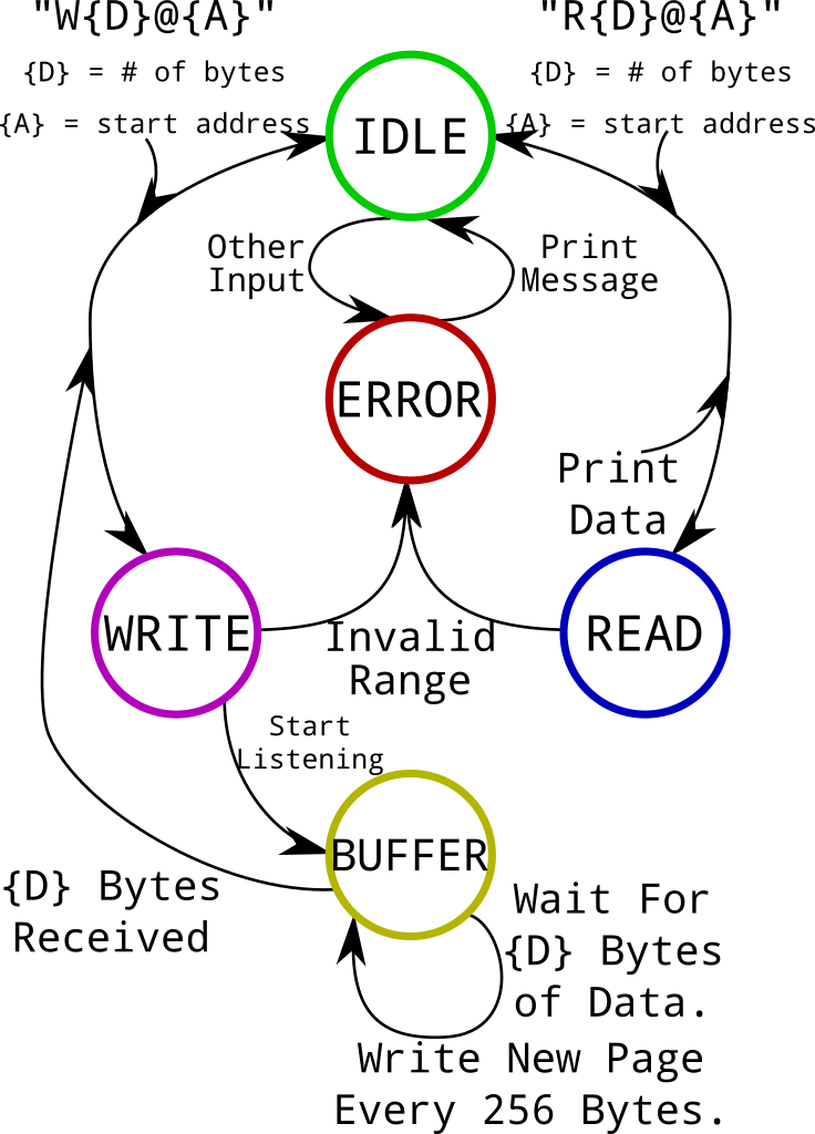
Flash Read / Write Program Flowchart
The program waits in an “Idle” state until it receives an “R” (Read) or “W” (Write) command including the number of bytes to read or write, along with a starting address. If an invalid command is received, the program prints an error message and returns to its “Idle” state.
A valid “Read” command will read the requested data and print it over the serial connection, followed by a \r\n newline.
“Write” commands are a bit more complicated; after a valid command is issued, the program will calculate which sectors the write will span, and erase them. Once the Flash chip is ready for writing, it prints RDY\r\n and then waits for a new page of data. At every page boundary, the program writes its buffered data to the Flash chip and prints RDY\r\n again when it is ready for a new page. When the whole operation finishes successfully, it prints OK\r\n.
This simple approach works for a few large files, but it can be prone to errors if you aren’t careful. First, the program does not save and restore data in sectors that it erases. So if your file only covers the first half of a page, the second half of that page will be erased even if it contains other data. Second, the transmitter and receiver both need to know when to stop and wait for page boundaries; you can’t just write a long stream of data in one burst.
So there’s plenty of room for improvement, but at least it’s not too long. Here’s the core program logic that I ended up with, not including interrupt setup or QSPI initialization:
  // Main loop: process commands and data.
  printf( "START\r\n" );
  while ( 1 ) {
    // Ready for a new command: print "RDY" and wait for a newline.
    printf( "RDY\r\n" );
    while ( !newline ) { __WFI(); }

    // Valid read or write commands start with 'R' or 'W'.
    if ( ( rx_buf[ 0 ] == 'W' ) || ( rx_buf[ 0 ] == 'R' ) ) {
      // Get the data length and starting address.
      // Values will be < 5,000,000,000.
      char dat_s[ 11 ] = { '\0', '\0', '\0', '\0', '\0', '\0', '\0', '\0', '\0', '\0', '\0' };
      char adr_s[ 11 ] = { '\0', '\0', '\0', '\0', '\0', '\0', '\0', '\0', '\0', '\0', '\0' };
      // 'Phase' variable. When an '@' character is encountered, it
      // moves from phase 0 (data length) to phase 1 (start address).
      int phase = 0;
      // Position in the destination C string.
      int pos = 0;
      // 'Invalid command' flag.
      int invalid = 0;

      // Iterate over the command string, extracting numeric values.
      for ( int i = 1; i < rx_pos; ++i ) {
        // 'Phase 0': Extract data length.
        if ( phase == 0 ) {
          // Move to phase 1 when an '@' character is reached.
          if ( rx_buf[ i ] == '@' ) {
            phase = 1;
            pos = 0;
          }
          else {
            // In ASCII, number values ('0' - '9') are 0x30 - 0x39.
            // Non-numeric parameters are invalid.
            if ( ( rx_buf[ i ] < 0x30 ) || ( rx_buf[ i ] > 0x39 ) ) {
              invalid = 1;
              break;
            }
            // Copy current character into the destination C string.
            dat_s[ pos ] = rx_buf[ i ];
            ++pos;
          }
        }
        // 'Phase 1': Extract start address.
        else {
          // '\r\n' marks the end of the command.
          if ( rx_buf[ i ] == '\r' ) { break; }
          // Copy the start address character if it is a number.
          else {
            if ( ( rx_buf[ i ] < 0x30 ) || ( rx_buf[ i ] > 0x39 ) ) {
              invalid = 1;
              break;
            }
            adr_s[ pos ] = rx_buf[ i ];
            ++pos;
          }
        }
      }

      // Print an error message if the command was invalid.
      if ( invalid ) {
        printf( "NOPE\r\n" );
      }
      // Process the read or write command.
      else {
        // Prepare values and convert strings to integers.
        rx_pos = 0;
        dat_s[ 10 ] = '\0';
        adr_s[ 10 ] = '\0';
        int dat_len = atoi( dat_s );
        int adr_pos = atoi( adr_s );
        // Commands with a data length of 0 bytes are invalid.
        if ( dat_len == 0 ) {
          printf( "NOPE0\r\n" );
        }
        // Process write command.
        else if ( rx_buf[ 0 ] == 'W' ) {
          // Receive and write data, one page at a time.
          // The last page which will be written to.
          int last_page = ( adr_pos + dat_len - 1 ) / 256;
          // Bytes remaining.
          int dat_left = dat_len;
          // Current write address.
          int cur_adr = adr_pos;
          // Address of the next page boundary.
          int next_page = ( cur_adr / 256 ) + 1;
          // Number of bytes to transfer in the current page write.
          int rx_len = dat_left;
          if ( ( cur_adr + dat_left ) > ( next_page * 256 ) ) {
            rx_len = ( next_page * 256 ) - cur_adr;
          }

          // Erase any sectors which contain data to be written.
          printf( "SE...\r\n" );
          for ( int i = ( cur_adr / 0x1000 );
                i < ( ( ( cur_adr + dat_len ) / 0x1000 ) + 1 );
                ++i ) {
            printf( "%d...\r\n", i );
            qspi_erase_sector( i );
          }

          // Receive one page of data at a time; print "RDY" when
          // the next page of data can be sent.
          for ( int i = cur_adr / 256; i < last_page + 1; ++i ) {
            printf( "RDY\r\n" );
            // Wait for the appropriate number of bytes.
            while ( rx_pos < rx_len ) { __WFI(); }
            rx_pos = 0;
            // Write the page of data.
            qspi_write_page( cur_adr, rx_len, ( uint8_t* )rx_buf );
            // Update bookkeeping values.
            cur_adr = next_page * 256;
            ++next_page;
            dat_left -= rx_len;
            if ( dat_left >= 256 ) { rx_len = 256; }
            else { rx_len = dat_left; }
          }

          // Done.
          printf( "OK\r\n" );
        }
        // Process read command.
        else if ( rx_buf[ 0 ] == 'R' ) {
          // Enable memory-mapped mode.
          QUADSPI->CR  &= ~( QUADSPI_CR_EN );
          QUADSPI->CCR &= ~( QUADSPI_CCR_INSTRUCTION );
          QUADSPI->CCR |=  ( 3 << QUADSPI_CCR_FMODE_Pos |
                             3 << QUADSPI_CCR_ADMODE_Pos |
                             3 << QUADSPI_CCR_DMODE_Pos |
                             3 << QUADSPI_CCR_IMODE_Pos |
                             0xEC << QUADSPI_CCR_INSTRUCTION_Pos |
                             6 << QUADSPI_CCR_DCYC_Pos );
          QUADSPI->CR  |=  ( QUADSPI_CR_EN );
          __asm( "NOP" );

          // Read data and print it out.
          uint8_t* qflash = ( uint8_t* )0x90000000;
          for ( int i = 0; i < dat_len; ++i ) {
            putchar( qflash[ i + adr_pos ] );
          }
          printf( "\r\n" );
          fflush( stdout );

          // Exit memory-mapped mode.
          QUADSPI->CR   &= ~( QUADSPI_CR_EN );
          QUADSPI->CCR  &= ~( QUADSPI_CCR_INSTRUCTION |
                              QUADSPI_CCR_FMODE |
                              QUADSPI_CCR_IMODE |
                              QUADSPI_CCR_DMODE |
                              QUADSPI_CCR_ADMODE |
                              QUADSPI_CCR_DCYC );
        }
      }

      // Done running the command; reset bookkeeping values.
      rx_pos = 0;
      newline = 0;
    }
    // Invalid commands return an error.
    else {
      // Print a response refusing the invalid command.
      printf( "NOPE: %s\r\n", rx_buf );
      rx_pos = 0;
      newline = 0;
    }
  }
You can also find a full project with a main.c file that includes the initialization logic in this post’s GitHub repository.
Basic Testing
You can test the program by connecting to the board’s serial connection and manually issuing a few commands. I’ve used screen in past tutorials, but I think miniterm.py is a better option for this program. It sends a full \r\n when you hit “enter”, and it’s a bit more user-friendly. You can install miniterm.py by installing the pyserial Python package, which we’ll use in the next section anyways.
If you load and run the program we discussed earlier via OpenOCD, you can issue a command like W4@0 to write four bytes of data at address zero. If you enter that, you should see the “sector erase” messages printed, followed by RDY. Type in four letters on your keyboard, and the program should print OK.
SE...
0...
RDY
OK
RDY
The program doesn’t echo your keystrokes back, so you have to enter a whole line without seeing your input reflected on the serial connection. To make sure that it worked, you can issue a command like R8@0 to read 8 bytes of data from address zero:
RDY
hexa����
RDY
I had entered “hexa” for the four bytes after the write command, and the remaining bytes are returning 0xFF since the whole sector was erased. Once you’re happy that those commands work, it’s time to use them to write an entire file’s worth of data, then read it back to verify a successful write.
Writing and Verifying a File
Python is a nice language to write simple “glue” programs with. Something like Rust or C would probably be faster, but using Python lets me avoid talking about toolchains, libraries, etc. Just make sure that you’ve installed a version of Python, and the pyserial package. We’ll also use the standard os and sys packages.
The first thing you’ll want to do is clear the serial input buffer. Your computer will buffer data as it arrives, and if you try to read from the pipe while that buffer has data in it, you might get data from before your program ran.
I saw this happen once while helping someone set up a Python script to read a UART sensor’s value; they wanted it to log every 10 seconds, but the sensor reported data every second. When we read the sensor’s value every 10 seconds, we would get results that seemed to be out of date or wrong, and it turned out that the computer was keeping 9 old values in its buffer for every one value that we read. You can manually clear the input buffer using the pyserial package like this:
# Python script to read / write / erase a board's QSPI Flash chip.
import os
import serial
import sys

PORT = '/dev/ttyACM0'
BAUD = 115200

# Reset the serial port's input buffer, otherwise data
# might be read from the past.
with serial.Serial( PORT, BAUD, timeout = 5 ) as tty:
  tty.reset_input_buffer()
It’s also a good idea to print a brief “help” or “usage” method if an invalid input is received, even with single-purpose scripts like this:
# If the input parameters aren't valid, print a help message.
# TODO: Verify parameter types too.
if len( sys.argv ) != 3:
  print( "Usage: python qspi_prog.py <start_address> <file_to_write>\r\n" )
Next, we can make sure that the starting address is a number by trying to convert it to an integer, and we can make sure that the target file path is valid by trying to get its size in bytes. This isn’t the best approach – among other things, the reported size of a file may not always be accurate – but it is short:
# Write a file and verify it by reading it back.
else:
  # Get the file size and address offset as numbers.
  fsize = os.path.getsize( sys.argv[ 2 ] )
  sadr = int( sys.argv[ 1 ] )

  # Print a message describing what the script will do.
  print( "Write %d bytes @ 0x%08X"%( fsize, sadr ) )
Then we can send a “write data” command in the format that we defined earlier:
  # Write and verify the file.
  with serial.Serial( PORT, BAUD, timeout = 5 ) as tty:
    # Send the "Write data" command.
    tty.write( "W{0}@{1}\r\n".format( fsize, sadr ).encode() )
And once the chip finishes erasing the required sectors, we can send the file data one page at a time:
    # Open the target file as a read-only binary file.
    with open( sys.argv[ 2 ], 'rb' ) as f:
      # Set up some intermediary values to track progress.
      dat_left = fsize
      read_len = 256 - ( sadr % 256 )
      pv = 0
      rxb = ""

      # Wait for the program to finish erasing sectors.
      while rxb != "RDY\r\n":
        rxb = tty.readline()

      # Send data one page at a time.
      while dat_left > 0:
        # File reads can't be larger than one Flash page (256B).
        if read_len > dat_left:
          read_len = dat_left

        # Read N bytes from the file, and write them to the serial connection.
        fbuf = f.read( read_len )
        tty.write( fbuf );

        # Update bookkeeping values.
        dat_left -= read_len
        read_len = 256
        pv += 1
        # Only print every hundredth page, for brevity.
        if pv % 100 == 0:
          print( "Page %d..."%pv )

        # Wait for the chip to respond after each page of data.
        rxb = tty.readline()

    # Done writing data; the target file gets closed here.
    print( "Done.\r\nVerifying..." )
In that code, I sometimes call tty.readline() and assume that it will respond with RDY or OK. This has the effect of ignoring errors, which makes the script more fragile, but it’s also a quick one-line way to wait for a response.
Once the file is written, we can verify it by reading the data back and comparing it to the file on disk. Since we opened the file using with open(...):, it will automatically be closed when that code block is exited. That means that we’ll have to re-open it to verify its contents:
    # Re-open the target file to verify the written data.
    fb = open( sys.argv[ 2 ], 'rb' )
Then we can use another loop to read and verify one 4KiB sector at a time, accounting for partially-filled sectors:
    # Set up values to track verification progress / status.
    prog = 0
    fail = 0
    # Verify data one 4KiB sector at a time.
    for i in range( ( ( fsize - 1 ) / 4096 ) + 1 ):
      # Wait for the chip to finish its previous command.
      rxb = tty.readline()

      # Calculate the number of bytes to read in this sector.
      read_len = 4096
      if fsize - prog < 4096:
        read_len = fsize - prog

      # Send the "Read byte" command.
      tty.write( "R{0}@{1}\r\n".format( read_len, sadr + prog ).encode() )
      # Read the response and its newline.
      bytes_in = tty.read( read_len )
      rxb = tty.readline()

      # Compare the received data to the target file.
      file_bytes = fb.read( read_len )

      # Mark failures, and print a message every 10 sectors.
      if bytes_in != file_bytes:
        print( "Fail: Sector %d does not match."%i )
        fail = 1
      if i % 10 == 0:
        print( "Checked sector %d"%i )

      # Update "progress" value.
      prog += read_len

    # Done verifying data; print a success or failure message.
    if fail:
      print( "Verification failed." )
    else:
      print( "Verification complete." )
You can find this script on GitHub along with the rest of this project. If you build the previous program and run it in RAM using the same steps as the basic “blink” example, you should be able to run the script to write arbitrary files to the board’s QSPI Flash chip. For example, write a few lines in a test.txt file and run:
>python qspi_prog.py 2 test.txt
Write 67 bytes @ 0x00000002
Done.
Verifying...
Checked sector 0
Verification complete.
Then verify the contents by entering something like R64@0 in miniterm.py (all while the RAM program is loaded and running):
>miniterm.py /dev/ttyACM0 115200
--- Miniterm on /dev/ttyACM0  115200,8,N,1 ---
--- Quit: Ctrl+] | Menu: Ctrl+T | Help: Ctrl+T followed by Ctrl+H ---
��This is a text file, and I'm too lazy to write something detai
RDY
Sounds about right. And since it was written at a 2-byte offset, the first two bytes are erased to 0xFF.
Conclusions
Loading programs into RAM is a good way to run ephemeral programs on a microcontroller, and code can also run significantly more quickly if it is executed from RAM compared to Flash. Most microcontrollers have much less RAM than Flash, but it’s still good to know how to write and run code like this.
It’s also good to know how to relocate the chip’s vector table into RAM; it’s worth doing that even when you’re running a program from Flash. RAM is faster to access, so you’ll have faster interrupt latencies across the board when the vector table is in RAM. Putting short interrupt handler functions in RAM lets them run more quickly, too.
And since this is a Cortex-M7 target, you also have the faster DTCM and ITCM RAM banks. Putting your stack in the DTCM section can help because of how frequently the stack is accessed, and putting your interrupt handler functions in the ITCM section should make them run faster. TCM banks also provide a deterministic upper bound on access times, which makes them useful for “hard real-time” applications. If you put an interrupt handler in ITCM RAM, you should be able to calculate a reliable upper bound on how long it will take to run.
Well, that’s about it; I hope this quick tour of STM32 RAM resources was helpful, but questions and comments are welcome as always! You can find projects containing the code presented here on GitHub.

