
If you’ve been reading the posts about STM32s that I’ve been writing, I owe you an apology. Usually when people write microcontroller tutorials, UART is one of the first peripherals that they talk about, and I’ve gone far too long without mentioning it. It is such a fundamental peripheral that I vaguely thought I’d already written about it until I got a couple of comments asking about it, so thank you for those reminders!
UART stands for “Universal Asynchronous Receiver / Transmitter”, and it is a very simple serial communication interface. In its most basic form, it only uses two data signals: “Receive” (RX) and “Transmit” (TX). Since it is asynchronous (no clock signal), both devices need to use the same “baud rate”, which is basically the transmission frequency measured in Hertz. If you have a baud rate of 9600, then you expect a new bit every 1 / 9600 of a second. (But technically, your actual transmission frequency will be slightly lower than the baud rate, because the standard includes extra “control” bits which are sent in addition to the actual data.)
One of the most common uses of UART is to transmit strings of text or binary data between devices. That, combined with the availability of cheap off-the-shelf USB / UART bridges, makes it a popular way to add some interactivity and a working printf(...) function to bare-metal applications.
And while a simple 2-wire UART connection is reliable enough for most purposes, there is also an extended USART standard which adds an optional “clock” line to synchronize the two devices’ timing; the extra “S” stands for “Synchronous”. The standards are otherwise very similar, so you might see UART and USART used interchangeably in some places. There are also a set of extra “flow control” signals, but I’m not going to talk about those or USART functionality in this post.
I will cover a few basic ways to use the STM32 UART peripherals, though:
- Setting up the
UARTperipheral to send / receive data one byte at a time. - Implementing the C standard library’s
printf(...)function to send text strings overUART - Using interrupts to receive data as it arrives.
- Setting up a “ring buffer” to handle continuous data reception.
If any of that sounds interesting, keep reading! The target hardware will be either an STM32L432KC “Nucleo-32” board or an STM32F103C8 “pill” board; they cost around $11 or $2-5 respectively. The “Nucelo” boards are easier to use, because they include a debugger. If you use a “pill” board, you’ll also need an ST-LINK debugger and a USB / UART bridge such as a CP2102 board. And these examples are all available in a GitHub repository, if you just want a quick reference.
Basic UART Setup
Most STM32 chips contain several USART peripherals, including simpler UART peripherals which do not support the extra “synchronization” clock signal. You’ll probably have at least 3 of them, but some larger chips have 8 or more since it is such a common interface. Like with other STM32 peripherals, you can check your chip’s datasheet to see which pins can be used with which peripherals.
For these examples, I’ll use the USART2 peripheral. If you’re using an STM32L432KC “Nucleo-32” board, pins A2 and A15 are connected to its built-in debugger which will forward the serial connection over the board’s USB connector. If you’re using an STM32F103C8 “pill” board, pins A2 and A3 are connected to the USART2 peripheral.
The first step, as usual, is to initialize the chip by setting up the core system clock. I set up this project similarly to the ones in my previous tutorials, with a Makefile capable of building the program for different targets. You can see how that works in the GitHub repository, but tl;dr, the Makefile defines different compilation flags depending on the target chip. This is one way to adjust your code for different hardware, but you can also write separate “port” files for each target chip when your project outgrows it:
// Standard library includes.
#include <stdint.h>
#include <stdio.h>
#include <string.h>

// Device header file.
#ifdef VVC_F1
  #include "stm32f1xx.h"
#elif VVC_L4
  #include "stm32l4xx.h"
#endif

uint32_t SystemCoreClock = 0;
extern uint32_t _sidata, _sdata, _edata, _sbss, _ebss;

// Reset handler: set the stack pointer and branch to main().
__attribute__( ( naked ) ) void reset_handler( void ) {
  // Set the stack pointer to the 'end of stack' value.
  __asm__( "LDR r0, =_estack\n\t"
           "MOV sp, r0" );
  // Branch to main().
  __asm__( "B main" );
}

/**
 * Main program.
 */
int main( void ) {
  // Copy initialized data from .sidata (Flash) to .data (RAM)
  memcpy( &_sdata, &_sidata, ( ( void* )&_edata - ( void* )&_sdata ) );
  // Clear the .bss section in RAM.
  memset( &_sbss, 0x00, ( ( void* )&_ebss - ( void* )&_sbss ) );

  #ifdef VVC_F1
    // Default clock source is the 8MHz internal oscillator.
    SystemCoreClock = 8000000;
  #elif VVC_L4
    // Enable floating-point unit.
    SCB->CPACR |= ( 0xF << 20 );
    // Default clock source is the "multi-speed" internal oscillator.
    // Switch to the 16MHz HSI oscillator.
    RCC->CR |=  ( RCC_CR_HSION );
    while ( !( RCC->CR & RCC_CR_HSIRDY ) ) {};
    RCC->CFGR &= ~( RCC_CFGR_SW );
    RCC->CFGR |=  ( RCC_CFGR_SW_HSI );
    while ( ( RCC->CFGR & RCC_CFGR_SWS ) != RCC_CFGR_SWS_HSI ) {};
    SystemCoreClock = 16000000;
  #endif

  // (...more code goes here...)

}
The floating-point unit is also enabled for STM32L4 targets, because it will be required by the standard library’s printf function later on. The FPU is part of the ARM Cortex-M CPU, so you won’t find much information about it in the STM32 reference manuals. Instead, check the ARM infocenter or the Cortex-M4 technical reference manual.
Next, we need to enable the peripheral clocks and configure the GPIO pins:
  #ifdef VVC_F1
    // Enable peripheral clocks: GPIOA, USART2.
    RCC->APB1ENR  |=  ( RCC_APB1ENR_USART2EN );
    RCC->APB2ENR  |=  ( RCC_APB2ENR_IOPAEN );
    // Configure pins A2, A3 for USART2.
    GPIOA->CRL    &= ( GPIO_CRL_MODE2 |
                       GPIO_CRL_CNF2 |
                       GPIO_CRL_MODE3 |
                       GPIO_CRL_CNF3 );
    GPIOA->CRL    |= ( ( 0x1 << GPIO_CRL_MODE2_Pos ) |
                       ( 0x2 << GPIO_CRL_CNF2_Pos ) |
                       ( 0x0 << GPIO_CRL_MODE3_Pos ) |
                       ( 0x1 << GPIO_CRL_CNF3_Pos ) );
  #elif VVC_L4
    // Enable peripheral clocks: GPIOA, USART2.
    RCC->APB1ENR1 |= ( RCC_APB1ENR1_USART2EN );
    RCC->AHB2ENR  |= ( RCC_AHB2ENR_GPIOAEN );
    // Configure pins A2, A15 for USART2 (AF7, AF3).
    GPIOA->MODER    &= ~( ( 0x3 << ( 2 * 2 ) ) |
                          ( 0x3 << ( 15 * 2 ) ) );
    GPIOA->MODER    |=  ( ( 0x2 << ( 2 * 2 ) ) |
                          ( 0x2 << ( 15 * 2 ) ) );
    GPIOA->OTYPER   &= ~( ( 0x1 << 2 ) |
                          ( 0x1 << 15 ) );
    GPIOA->OSPEEDR  &= ~( ( 0x3 << ( 2 * 2 ) ) |
                          ( 0x3 << ( 15 * 2 ) ) );
    GPIOA->OSPEEDR  |=  ( ( 0x2 << ( 2 * 2 ) ) |
                          ( 0x2 << ( 15 * 2 ) ) );
    GPIOA->AFR[ 0 ] &= ~( ( 0xF << ( 2 * 4 ) ) );
    GPIOA->AFR[ 0 ] |=  ( ( 0x7 << ( 2 * 4 ) ) );
    GPIOA->AFR[ 1 ] &= ~( ( 0xF << ( ( 15 - 8 ) * 4 ) ) );
    GPIOA->AFR[ 1 ] |=  ( ( 0x3 << ( ( 15 - 8 ) * 4 ) ) );
  #endif
I don’t think I’ve talked about STM32F1 GPIO pin configurations before, and they work a little differently from most other STM32 lines. Each pin has four configuration bits spread across two 32-bit registers. CRL configures pins 0-7, and CRH configures pins 8-15. The pin settings are spread across two “configuration” bits and two “mode” bits:
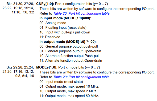
STM32F1 GPIO pin configurations
Notice that the RX pin (A3) is configured as a floating input rather than an alternate-function output. Sometimes it can be tricky to get the STM32F1 pin configurations right for different peripherals, so keep in mind that the “alternate function” configurations are not always used with “input” peripheral signals.
Once you’ve enabled the peripheral and set up the GPIO pins, you’re almost done. The UART peripherals’ reset configurations match the most common settings of 8 bits per byte, no parity checks, and 1 “stop bit”. If you need a non-standard configuration, you can find more information about these settings in the “USART registers” section of your chip’s reference manual. The STM32F1 and STM32L4 peripherals are slightly different, but in both cases, the parity settings and number of bits per byte are in CR1 and the number of stop bits are in CR2.
You’ll also need to set the baud rate so that the peripheral knows how quickly it should send and receive data. There’s a special BRR Baud Rate Register which contains a factor to divide the core clock speed by in order to get the desired baud rate. The STM32L4 peripheral sets its baud rate equal to the core clock rate divided by the BRR register’s value, but the STM32F1 peripheral is a bit more complex. It divides by (BRR * 16), with the register’s 4 lowest bits representing a fractional value. So given the SystemCoreClock values set above, we can configure a baud rate of 9600 like this:
  // Set the baud rate to 9600.
  uint16_t uartdiv = SystemCoreClock / 9600;
  #ifdef VVC_F1
    USART2->BRR = ( ( ( uartdiv / 16 ) << USART_BRR_DIV_Mantissa_Pos ) |
                    ( ( uartdiv % 16 ) << USART_BRR_DIV_Fraction_Pos ) );
  #elif VVC_L4
    USART2->BRR = uartdiv;
  #endif
(In computing, the term “Mantissa” is often used to describe the numbers left of a decimal point in a fractional number.)
The way that the reference manuals describe baud rate configurations can be a little confusing, but they do include a few example calculations under a “baud rate generation” sub-heading of the “USART functional description” section.
Finally, you can turn the peripheral on by setting the UE (USART Enable), TE (Transmit Enable), and RE (Receive Enable) bits in the CR1 register:
  // Enable the USART peripheral.
  USART2->CR1 |= ( USART_CR1_RE | USART_CR1_TE | USART_CR1_UE );
And that’s it! You are now ready to transmit and receive data. You can test the peripheral with a simple “echo” program which repeats bytes from its “receive” line onto its “transmit” line:
  // Main loop: wait for a new byte, then echo it back.
  char rxb = '\0';
  while ( 1 ) {
    // Wait for a byte of data to arrive.
    #ifdef VVC_F1
      while( !( USART2->SR & USART_SR_RXNE ) ) {};
      rxb = USART2->DR;
    #elif VVC_L4
      while( !( USART2->ISR & USART_ISR_RXNE ) ) {};
      rxb = USART2->RDR;
    #endif

    // Re-transmit the received byte.
    #ifdef VVC_F1
      while( !( USART2->SR & USART_SR_TXE ) ) {};
      USART2->DR = rxb;
    #elif VVC_L4
      while( !( USART2->ISR & USART_ISR_TXE ) ) {};
      USART2->TDR = rxb;
    #endif
  }
The TXE (Transmitter Empty) bit will be set when the peripheral’s “transmit” register is ready to accept new data; you can also check the TC (Transfer Complete) bit to see when the peripheral has finished sending all of its pending data. And similarly, the RXNE (Receiver Not Empty) bit will be set when the peripheral’s “receive” register contains a new byte of data. The TXE bit is automatically reset when you write a new byte of data to the UART data register, and the RXNE bit is automatically reset when you read a byte from it. There is a shared DR Data Register in the STM32F1 peripheral, and separate TDR / RDR Transmit / Receive Data Registers in the STM32L4 one.
And if you don’t want to create a project and copy / paste all of this code, you can find a full example project on GitHub.
Connecting Your Computer to a UART Interface
If you flash this example “echo” program to your board and connect to the UART interface through a serial terminal on your computer, you should be able to type into the terminal and see your keystrokes repeated back. But how do you connect to the serial interface from you computer? (Feel free to skip down to the “Implementing ‘printf'” section if you already have a preferred way of doing this.)
If you are using one of ST’s “Nucleo” boards, you don’t need any more hardware; you can just plug in a micro-USB cable. The pins that we used in the example are connected to the built-in debugger’s “virtual COM port”, which forwards the serial connection over the debugger’s USB interface. For more information, check the “USART virtual communication” section of the user manual.
If you are using a cheap STM32F103C8-based board, you’ll need to connect a debugger to upload the program and a USB / UART bridge to interact with the board from your computer. Connect the ground pins of both boards, and wire each side’s TX pin to the other side’s RX pin. You’ll also need to provide power to the board, either from your bridge chip or a separate USB cable. Remember to avoid giving the board more than one power supply at a time; for example, don’t plug in a USB cable while you are providing a 3.3V supply from somewhere else.
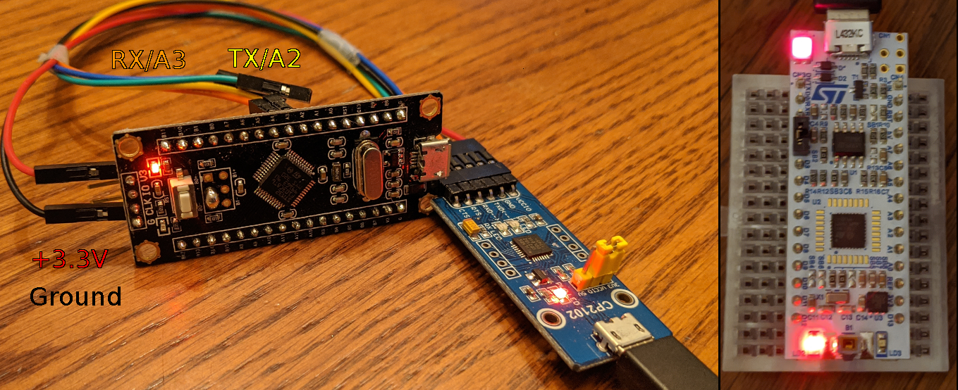
Cheap STM32F103C8 boards require an external USB / UART converter (left), while “Nucleo” boards can simply be plugged in (right).
The CP2102 board in that picture is from Waveshare, but you can also make your own or find other options on sites like AliExpress / eBay / Tindie / etc. Once everything is plugged in, you should be able to see a new serial resource in your computer’s OS.
Connecting From Linux
If you’re on Linux, you can list the relevant system resources with ls /dev/tty*. You want the one that shows up only while your device is plugged in; it will probably be called either ttyACMx or ttyUSBx, where “x” is a number.
There are many ways to access a serial port in Linux, but the GNU screen program is simple and easily available in most distributions. It is often used by web developers and sysadmins to keep terminal sessions running on remote hosts across logins, but you can also use it to open a serial pipe with something like:
screen /dev/ttyACM0 9600
The last option specifies the baud rate. If it prints “[screen is terminating]” and exits immediately, you might need to run it as root or with sudo. You’ll see a blank screen when the connection is opened, but when you press a key, that character will be transmitted over the UART connection. And when a character is received, it will be printed on the screen. If you’ve flashed the “echo” program above, you should be able to type on the keyboard and see your keystrokes printed back.
Unfortunately, it’s a little bit tricky to quit screen once you’ve opened a connection. You need to hit ctrl + a, followed by \, followed by y. I think that’s one of those legacy things that made more sense in the ’70s; apparently the program tries to have similar key bindings to the venerable VT100.
Connecting From Windows
If you’re using Windows, you can find your device’s port name and number in the “Device Manager” system application. Look under the “Ports (COM & LPT)” section for a resource which appears only when your device is plugged in. It will probably be called COMx, where “x” is a number.
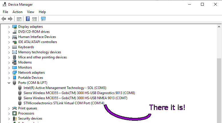
This device showed up as COM14 in Windows.
Windows also has a handful of popular programs which can connect to serial interfaces. TeraTerm is one of them, with a simple and easy-to-use GUI. To open a new connection, open the program and hit “Cancel” on the initial dialog. Then click on the “Setup” toolbar menu and select “Serial Port…”, at which point a dialog should pop up:
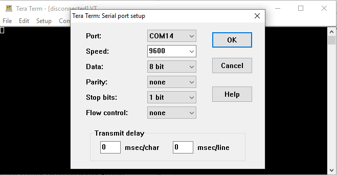
TeraTerm serial port setup
Under the “Port:” menu, select ther resource ID that you found in the Device Manager; in my case, it was COM14. You can also configure the baud rate (“Speed”) and other settings, but we’re using the default configuration of 8 bits per byte, 1 stop bit, and no parity check. Once you hit “OK”, the program should connect and act similarly to screen: characters get sent over the TX line as you type them in, and characters received over the RX line will be displayed in the terminal. So again, you should see your keystrokes printed back if you’ve flashed the previous “echo” program onto your board and connected it properly.
Implementing ‘printf’
You can add support for the C standard library’s printf(...) function to your project by overriding the standard library’s _write(...) function to transmit characters over UART:
// Override the 'write' clib method to implement 'printf' over UART.
int _write( int handle, char* data, int size ) {
  int count = size;
  while( count-- ) {
    #ifdef VVC_F1
      while( !( USART2->SR & USART_SR_TXE ) ) {};
      USART2->DR = *data++;
    #elif VVC_L4
      while( !( USART2->ISR & USART_ISR_TXE ) ) {};
      USART2->TDR = *data++;
    #endif
  }
  return size;
}
…And that’s all you need to do. The standard library code still works in a bare-metal environment, but only with the help of some important system calls which are usually provided by an operating system. _write is one of those system calls, so once you implement it, you can use standard library functions which depend on it. Try this new “echo” program:
  // Main loop: wait for a new byte, then echo it back.
  char rxb = '\0';
  while ( 1 ) {
    // Wait until a new character is received.
    #ifdef VVC_F1
      while( !( USART2->SR & USART_SR_RXNE ) ) {};
      rxb = USART2->DR;
    #elif VVC_L4
      while( !( USART2->ISR & USART_ISR_RXNE ) ) {};
      rxb = USART2->RDR;
    #endif

    // Print a line containing the newly-received character.
    printf( "RX: %c\r\n", rxb );
  }
You can find a project with this new code on GitHub. If you flash the program and connect to the serial interface, you should see a new line saying RX: <key> for every key that you press. But if you press keys very quickly or copy / paste a long message, the application will miss some characters. What gives?
At a baud rate of 9600, it can take awhile to finish sending a string of text. And since the “transmit” and “receive” logic are both blocking, your program might not be able to keep up with rapid inputs. We could try using a higher baud rate to send data more quickly, but a better solution is to use a hardware interrupt for the “receive” logic; we’ll do that in the next section.
First, though, a quick note about printf. If you work on larger projects, it is good practice to add print statements for logging, debugging, and error reporting. But as we have just seen, printing messages over UART can take a long time, so you might also want to add a “debug” build flag which can enable or disable optional logging statements. Preprocessor statements are an easy way to accomplish that:
#ifdef DEBUG
  #define LOG( msg... ) printf( msg );
#else
  #define LOG( msg... ) ;
#endif

// (Later in your code)
LOG( "Number: %d\r\n", 42 );
If you use a variadic macro like that, the logging statement will only be included in the program if -DDEBUG is passed into the compiler, or if #define DEBUG 1 is included in one of the source files. If you’re using a Makefile like the one in the reference repository, you can add this sort of flag to the CFLAGS variable. And once you’re happy with how the program works, you can build it without the DEBUG flag to save space and speed things up.
You might also notice that the compiled program is much larger with printf included (1-2KB vs. 24-28KB at the time of writing). Standard library functions can pull in a lot of extra code, but it would be annoying, time-consuming, and error-prone to write your own comprehensive print function with formatting. Life is full of tradeoffs.
Receiving Real-Time Data with Interrupts
Getting back to the problem of overrun errors, it’s usually good to avoid listening for incoming data in a busy-loop. Your application will have other things to do, and we’ve seen how easy it is to miss data if you only check on the peripheral periodically. So let’s enable the UART “receive” interrupt, and store incoming data as soon as it arrives.
I wrote about how to listen for button presses using interrupts a little while ago, and the process to set up UART interrupts looks very similar. The NVIC “interrupt controller” peripheral takes a couple of extra steps to configure, though. Depending on which board you chose to follow along with, you’ll be using either an ARM Cortex-M3 or Cortex-M4 CPU core. My earlier “interrupts” tutorial was written for boards which used simpler Cortex-M0 or Cortex-M0+ CPUs, and they have slightly simpler NVIC peripherals with a single “priority” setting for each interrupt.
The more complex Cortex-M cores support two separate “priority” and “sub-priority” settings to provide more granular control over interrupt pre-emption. You can read more about these priority settings in this article on one of ARM’s blogs, but to avoid confusion, I usually ignore “sub-priority” settings by configuring the whole priority field as “preempt priority” bits:
// Setup the NVIC to enable interrupts.
// Use 4 bits for 'priority' and 0 bits for 'subpriority'.
NVIC_SetPriorityGrouping( 0 );
// UART receive interrupts should be high priority.
uint32_t uart_pri_encoding = NVIC_EncodePriority( 0, 1, 0 );
NVIC_SetPriority( USART2_IRQn, uart_pri_encoding );
NVIC_EnableIRQ( USART2_IRQn );
The NVIC_EncodePriority call translates your desired “priority / sub-priority” values into a single value that the interrupt controller will understand, depending on how many bits are assigned to each setting. With zero bits assigned to the “sub-priority” setting, that value can be left at zero. And remember, a lower “priority” value indicates a higher urgency. I set the UART interrupt to have the second-highest priority level, 1, because it needs to be executed quickly to avoid missing incoming data. These settings don’t really matter when your program only uses a single interrupt, but that’s pretty uncommon outside of examples and demonstrations.
Defining the interrupt handler works the same as before; you just declare a void function with no arguments and the same name as the corresponding entry in the vector table. The interrupt request function is responsible for handling every type of UART peripheral interrupt, but they all start in a “disabled” state. So if you want to use one, you need to enable it in the UART peripheral first. We’ll want to use the RXNEIE interrupt flag, which triggers an interrupt whenever the RXNE bit is set. So first, you’ll need to replace the CR1 register logic from this:
USART2->CR1 |= ( USART_CR1_RE | USART_CR1_TE | USART_CR1_UE );
To this:
  USART2->CR1 |= ( USART_CR1_RE |
                   USART_CR1_TE |
                   USART_CR1_UE |
                   USART_CR1_RXNEIE );
Then you can write an interrupt handler to store incoming bytes of data as they arrive:
// (Near the top of main.c)
volatile char rxb = '\0';

// (...program code goes here...)

// USART2 interrupt handler
void USART2_IRQn_handler( void ) {
  #ifdef VVC_F1
    // 'Receive register not empty' interrupt.
    if ( USART2->SR & USART_SR_RXNE ) {
      // Copy new data into the buffer.
      rxb = USART2->DR;
    }
  #elif VVC_L4
    // 'Receive register not empty' interrupt.
    if ( USART2->ISR & USART_ISR_RXNE ) {
      // Copy new data into the buffer.
      rxb = USART2->RDR;
    }
  #endif
}
Finally, your main program loop can be a bit simpler:
  // Main loop: wait for a new byte, then echo it back.
  while ( 1 ) {
    __WFI();
    putchar( rxb );
    fflush( stdout );
  }
The __WFI(); function is located in one of the CMSIS header files, which are #included by the STM32 device header file. It tells the chip to halt until an interrupt triggers, which is a simple way to use a bit less energy while the chip is idle. It is very general, though: it cannot wait for a particular type of interrupt. Fortunately, only one interrupt is active in this example, so we can safely assume that the chip will sleep until it receives a new character over UART.
The putchar standard library function prints a single character using the _write system call that we implemented earlier.
The fflush standard library function forces the program to print any buffered writes. Usually this is done whenever a newline is printed, but when you write one character at a time, the actual “printing” logic can get deferred. You’d also need to call fflush after a statement like printf( "%c", rxb ) if you wanted to ensure that the text is printed immediately.
You can find a full project implementing this code on GitHub.
This is much more reliable, but it still only receives one character at a time. The peripheral won’t encounter overrun errors anymore, but the application might still miss a character if it doesn’t process them quickly enough. We could try reading characters into a static buffer, but that can be dangerous; the buffer might overflow, which is a very common source of security and stability issues.
Continuous Transfers with Ring Buffers
Fortunately, there is a simple way to buffer arbitrarily-sized inputs without risking corrupted memory: a “ring buffer”. Wikipedia calls it a “circular buffer”, and they do a much better job of explaining the concept than I could.
Basically, you set up a statically-allocated buffer and write to it continuously, jumping back to the beginning when the buffer fills up. The data structure keeps track of two separate “read” and “write” pointers: when you read a character out of the buffer, you increment the “read” pointer and loop back to the beginning when it reaches the end. And when you write a character to the buffer, you increment the “write” pointer and loop back if necessary. Sometimes people call these “head” and “tail” pointers; if you think of it like that, the data structure works like an ouroboros.
When the “write” pointer equals the “read” pointer, the buffer is either empty (if the “read” pointer just incremented) or full (if the “write” pointer just incremented). The number of characters in the buffer can be inferred by observing the difference between the “read” and “write” pointers, but you need to account for the fact that both pointers can “loop around” from the end of the buffer back to the beginning.
If you receive a message that is too long or fail to process an incoming data stream quickly enough, you can still miss data when the “write” pointer leap-frogs the “read” pointer. But you won’t have data spilling over into areas of memory where it shouldn’t be, and you won’t need to repeatedly clear out or re-allocate the same buffer. Here’s an example implementation of a ring buffer which you can fit into a single ringbuf.h header file:
/*
 * Minimal statically-allocated ringbuffer.
 */
#ifndef __VVC_RINGBUF
#define __VVC_RINGBUF

// Simple ring buffer.
typedef struct {
  int len;
  volatile char* buf;
  volatile int  pos;
  volatile int  ext;
} ringbuf;

// Helper macro to write to a buffer.
#define ringbuf_write( rb, x ) \
  rb.buf[ rb.ext ] = x; \
  if ( ( rb.ext + 1 ) >= rb.len ) { rb.ext = 0; } \
  else { rb.ext = rb.ext + 1; }

// Read from a buffer. Returns '\0' if there is nothing to read.
static inline char ringbuf_read( ringbuf* buf ) {
  if ( buf->pos == buf->ext ) { return '\0'; }
  char read = buf->buf[ buf->pos ];
  buf->pos = ( buf->pos < ( buf->len - 1 ) ) ? ( buf->pos + 1 ) : 0;
  return read;
}

#endif
It’s a little rough around the edges, and it doesn’t do any fancy error handling, but it seems to work well enough for simple applications. You can use it by including the header file and defining a ringbuf struct near the other global variables like SystemCoreClock:
// (Near the top of main.c)
#include "ringbuf.h"

#define RINGBUF_SIZE ( 128 )
volatile char rb_buf[ RINGBUF_SIZE + 1 ];
ringbuf rb = {
  len: RINGBUF_SIZE,
  buf: rb_buf,
  pos: 0,
  ext: 0
};
volatile int newline = 0;
Usually it’s bad practice to stuff your whole project into a single main.c file, but these are simple examples and I think that talking about project directory structures can distract from the information which is actually important.
Anyways, next you can re-write your interrupt handler function to use the ring buffer:
// USART2 interrupt handler
void USART2_IRQn_handler( void ) {
  #ifdef VVC_F1
    // 'Receive register not empty' interrupt.
    if ( USART2->SR & USART_SR_RXNE ) {
      // Copy new data into the buffer.
      char c = USART2->DR;
      ringbuf_write( rb, c );
      if ( c == '\r' ) { newline = 1; }
    }
  #elif VVC_L4
    // 'Receive register not empty' interrupt.
    if ( USART2->ISR & USART_ISR_RXNE ) {
      // Copy new data into the buffer.
      char c = USART2->RDR;
      ringbuf_write( rb, c );
      if ( c == '\r' ) { newline = 1; }
    }
  #endif
}
And you can write a main loop to wait for an entire line of data to be received before printing the buffer contents:
  // Main loop: wait for a new byte, then echo it back.
  while ( 1 ) {
    while ( newline == 0 ) {
      __WFI();
    }
    while ( rb.pos != rb.ext ) {
      putchar( ringbuf_read( &rb ) );
    }
    printf( "\n" );
    newline = 0;
  }
If you flash that program and connect to the serial interface, you should be able to type into the console and only see your keystrokes after pressing “enter” or “return”. If you type in a message longer than 128 characters, the “write” pointer will leap-frog the “read” pointer and you won’t see the first part of what you typed in. But this is a simple way to receive blocks of data without corrupting memory if an overflow occurs, and you can detect impending overflows by comparing the “read” and “write” pointers when data is written.
Again, you can find a project with this code on GitHub.
Conclusions
Well I think that’s enough for now, although there is a lot more to these peripherals.
If all you need is a printf function, you can omit the “receive” logic to simplify your code. When you just need to transmit data, it’s perfectly fine to only configure the TX GPIO pin and leave the USART_CR1_RE bit un-set. Likewise, you can enable only the RX line if your program just needs to listen. And if you want to write a more efficient _write method, there is also a TXEIE interrupt which triggers when the peripheral is ready to accept a new byte of data.
I should also mention that modern devices are moving away from using 9600 as a standard baud rate. As microcontrollers have gotten faster, higher-speed UART has become more common, and these days a baud rate of 115200 is often used with devices that run faster than ~10-20MHz. But you might still need to use a slower baud rate if you expect to communicate over very long wires or in an electromagnetically noisy environment. Parity checks can also help if you expect to have problems with noise.
Anyways, I hope that this quick introduction covered enough of the basics to help you interact with generic UART devices and add logging or “print debugging” to your projects.

