
STM32 Baremetal Examples
“Bare Metal” STM32 Programming (Part 7): Embedded C++ Inheritance
As you start to re-use components like sensors and displays, you might start to get frustrated with how long it takes to set up new projects. Copying and cleaning code between old working examples and new ideas can be time-consuming and tedious. It’s much easier to simply copy a few portable library files around. While there are plenty of existing libraries for these sorts of peripherals and external devices, it’s good to learn how to write your own, and this is also a good way to demonstrate a few ‘gotchas’ that you should be aware of when using C++ in an embedded application.
In this tutorial, we will walk through setting up a couple of object-oriented classes to represent a common communication ‘I/O’ peripheral model:
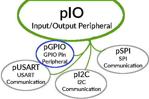
One example of what a simple common communication model could look like.
For simplicity’s sake, I’ll only cover a class for a bank of GPIO pins to demonstrate the core requirements for using C++ in an embedded application, but you can also find similar classes for the I2C peripheral and an SSD1306 OLED display in the example Github repository’s reference implementation of the concepts presented in this tutorial.
“Bare Metal” STM32 Programming (Part 6): Multitasking With FreeRTOS
In a previous tutorial, we walked through the process of setting up a hardware interrupt to run a function when a button was pressed or a dial was turned. Most chips have a broad range of hardware interrupts, including ones associated with communication and timer peripherals. There is also a basic ‘SysTick’ timer included in most ARM Cortex-M cores for providing a consistent timing without needing to count CPU cycles.
One good use of that evenly-spaced timing is to run a Real-Time Operating System (often called an ‘RTOS’) to process several tasks in parallel. As you add more parts to your projects, it will become awkward to communicate with them all using a simple ‘while’ loop. And while hardware interrupts can help, it’s usually good to do as little as possible inside of an interrupt handler function.
So let’s use FreeRTOS, an MIT-licensed RTOS, to run a couple of tasks at the same time. To demonstrate the concept, we’ll run two ‘toggle LED’ tasks with different delay timings to blink an LED in an irregular pattern.

Example LED timing with two ‘toggle’ tasks delaying for different amounts of time.
This example will also add support for some faster microcontrollers; the STM32F103C8 and STM32F303K8, which are Cortex-M3 and -M4F cores respectively. The F103C8 is available on cheap ‘blue pill‘ and ‘black pill‘ boards, and ST sells a ‘Nucleo’ board with the F303K8. Both of those chips can run at up to 72MHz, and they can also get more done per cycle since they have larger instruction sets. And as usual, there is example code demonstrating these concepts on Github.
Drawing to a Small TFT Display: the ILI9341 and STM32
As you learn about more of your microcontroller’s peripherals and start to work with more types of sensors and actuators, you will probably want to add small displays to your projects. Previously, I wrote about creating a simple program to draw data to an SSD1331 OLED display, but while they look great, the small size and low resolution can be limiting. Fortunately, the larger (and slightly cheaper) ILI9341 TFT display module uses a nearly-identical SPI communication protocol, so this tutorial will build on that previous post by going over how to draw to a 2.2″ ILI9341 module using the STM32’s hardware SPI peripheral.
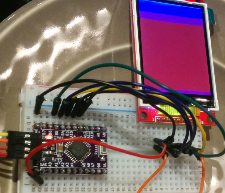
An ILI9341 display being driven by an STM32F0 chip. Technically this isn’t a ‘Nucleo’ board, but the code is the same.
We’ll cover the basic steps of setting up the required GPIO pins, initializing the SPI peripheral, starting the display, and then finally drawing pixel colors to it. This tutorial won’t read any data from the display, so we can use the hardware peripheral’s MISO pin for other purposes and leave the TFT’s MISO pin disconnected. And as with my previous STM32 posts, example code will be provided for both the STM32F031K6 and STM32L031K6 ‘Nucleo’ boards.
“Bare Metal” STM32 Programming (Part 5): Timer Peripherals and the System Clock
As you start to create microcontroller projects with more complicated logic, it probably won’t take long before you to want to add some sort of time-based functionality. How should you ask your chip to do something on a schedule?
These days, we don’t have to count clock cycles in ‘delay’ methods. The STM32 line of chips have a variety of “timer” peripherals available, and they are flexible enough to use for all kinds of different things. The “advanced control” timer peripheral is particularly complicated and I won’t try to cover it in this quick overview, but the basic and general-purpose timers are easy to get started with for simple counters and interrupts.
In this tutorial, we will write code to enable a hardware interrupt triggered by a timer peripheral, and use that to blink an LED. Just like the last couple of posts in this series, the STM32F031K6 and STM32L031K6 chips will be used to demonstrate these concepts. Since this tutorial will only use a single LED, you won’t need anything other than an affordable “Nucleo” board with one of those chips and a micro-USB cable:
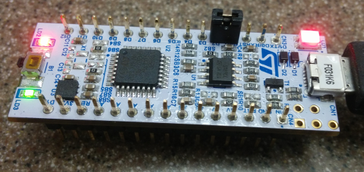
You don’t even need a breadboard!
You can double-check that the clock speeds are what we expect by counting the LED’s on/off timings against a clock. It should change about 60 times every minute with the timer set to 1 second, although the internal oscillator is not quite as precise as an external “HSE” crystal oscillator would be. As usual, an example project demonstrating this code is available in a Github repository.
When is Now? The DS3231 Real-Time Clock
Time may be an artificial construct, but try telling your boss that ‘Monday’ has no meaning. It is useful for a program to be able to schedule actions for a certain date, display the current time on a clock or calendar, or perform other tasks which use weird units of time like ‘seconds’ or ‘days’. For those types of tasks, an embedded developer might reach for an ‘RTC’ device, which stands for ‘Real-Time Clock’. They provide a way to keep accurate time, often with features like backup power supplies. Many RTCs also offer ‘wakeup’ alarms for other devices, so they are especially useful in energy-efficient designs.
The STM32 line of chips which I’ll continue to use in this tutorial have a built-in RTC peripheral, but they require an external 32.768KHz ‘LSE’ (Low-Speed External) crystal oscillator to keep accurate time. Also, managing the STM32’s backup power supply is sort of complicated.
Instead, this tutorial will walk through using the ‘I2C’ peripheral on an STM32 chip to communicate with a cheap DS3231 RTC module. Specifically, I will talk about a widely-available board labeled ZS-042, which includes 4KB of EEPROM on its I2C bus and space for a “coin cell” battery to provide several years of backup power. But the same commands should work with other DS3231 boards, such as the smaller ones in the upper-left here:
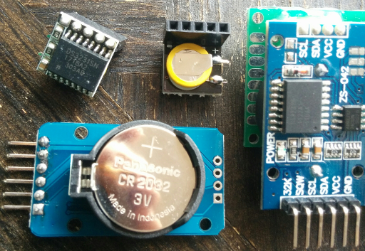
A handful of DS3231 modules and their backup batteries.
An example project demonstrating the concepts outlined in this post using either an STM32F031K6 or STM32L031K6 “Nucleo” board is available on Github.
“Bare Metal” STM32 Programming (Part 4): Intro to Hardware Interrupts
In a previous entry in this tutorial series, I tried to walk through some basic steps for writing an example STM32 program which toggled an LED on and off when a button is pressed. But that program only checked the button’s status once every cycle of the ‘main’ loop, and in a complex application each loop iteration could take a fairly long time. If a button press were very short and our application was busy for a long time, the program could miss the input.
When you want to respond to input very quickly and consistently on a microcontroller, it is usually a good idea to use a ‘hardware interrupt’ to run some code when certain hardware events are detected. In this tutorial, we will look at the STM32’s ‘EXTI’ interrupt lines, which can be set to trigger when the state of a GPIO pin changes.
And once we have a simple ‘button press’ interrupt triggering, we can easily demonstrate a real-world use by extending it to listen for faster inputs such as “rotary encoder” dials:
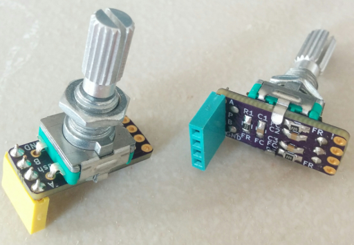
A couple of “rotary encoder” dials – the small resistors and capacitors on the back are for debouncing.
This type of dial ‘clicks’ in small steps when turned in either direction; they are nice tactile inputs, but it can be difficult to read them without hardware interrupts because of the large number of rapid pulses that they can generate when you twist them. So let’s get started!
“Bare Metal” STM32 Programming (Part 3): LEDs and Buttons!
In a previous post, I walked through creating a basic project for an ‘STM32F031K6’ microcontroller to boot the chip into a ‘main’ C method. But the actual program didn’t do much, so in this post we will learn how to use the STM32’s ‘GPIO’ peripheral to listen for a button press and blink an LED.
The ‘Nucleo’ boards provided by ST have an LED already built into the board, but they don’t have a button (besides the reset one,) so we’ll need to connect one externally:
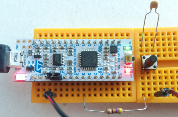
‘Nucleo’ STM32F031K6 board with a button.
The green ‘LD3’ LED is attached to pin B3 on the board. The 100nF capacitor across the button should help reduce noise, one side of the button connects to ground through a jumper wire, and I put a 470Ω resistor between the other side of the button and pin B1.
Strangely, the B1 pin is labeled ‘D6’ on the Nucleo boards; I think that ST wanted to use the same footprint and labeling as the popular Arduino Nano. You can find the actual pin mappings in section 6.11 of this reference document, or they’re also printed on the informational card that comes with the board. The resistor and capacitor are both optional – they’re just a very simple form of debouncing. Next up, the code!