
As you learn about more of your microcontroller’s peripherals and start to work with more types of sensors and actuators, you will probably want to add small displays to your projects. Previously, I wrote about creating a simple program to draw data to an SSD1331 OLED display, but while they look great, the small size and low resolution can be limiting. Fortunately, the larger (and slightly cheaper) ILI9341 TFT display module uses a nearly-identical SPI communication protocol, so this tutorial will build on that previous post by going over how to draw to a 2.2″ ILI9341 module using the STM32’s hardware SPI peripheral.
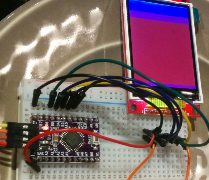
An ILI9341 display being driven by an STM32F0 chip. Technically this isn’t a ‘Nucleo’ board, but the code is the same.
We’ll cover the basic steps of setting up the required GPIO pins, initializing the SPI peripheral, starting the display, and then finally drawing pixel colors to it. This tutorial won’t read any data from the display, so we can use the hardware peripheral’s MISO pin for other purposes and leave the TFT’s MISO pin disconnected. And as with my previous STM32 posts, example code will be provided for both the STM32F031K6 and STM32L031K6 ‘Nucleo’ boards.
Step 0: RCC Setup
As with most STM32 projects, the first thing we should do is enable the peripherals that we will use. In this case, that’s just GPIOA, GPIOB, and SPI1. As in previous STM32 posts, I will use the device header files provided by ST for basic peripheral variable definitions, and determine the target chip from definitions passed in from the Makefile:
#ifdef VVC_F0
  RCC->AHBENR   |= RCC_AHBENR_GPIOAEN;
  RCC->AHBENR   |= RCC_AHBENR_GPIOBEN;
#elif  VVC_L0
  RCC->IOPENR   |= RCC_IOPENR_IOPAEN;
  RCC->IOPENR   |= RCC_IOPENR_IOPBEN;
#endif
RCC->APB2ENR |= RCC_APB2ENR_SPI1EN;
Step 1: GPIO Setup
With the peripherals powered on, we need to set up the GPIO pins used for communicating with the screen. To power the SSD1331 display in my previous tutorial, we configured all of the pins as ordinary push-pull outputs; as a quick refresher, we’ll use the SCK (Clock), MOSI (Data output), CS (Chip Select), D/C (Data or Command?), and RST (Reset) pins. The only difference with using the hardware peripheral is that we should configure the MOSI and SCK pins as ‘alternate function’ with high-speed output.
There are actually multiple sets of pins mapped to the SPI1 peripheral, even on the 32-pin STM32xKx chips. I’ll use pin B3 for SCK and pin B5 for MOSI. Pin B4 is mapped to MISO, but I’ll use it as a general-purpose output to drive the D/C pin on the TFT. As long as the MISO pin is not configured as ‘alternate function’, the peripheral will ignore it and we can use pin B4 as a normal GPIO pin. Finally, pins A12 and A15 are mapped to CS and RST respectively:
// Define GPIOB pin mappings for software '4-wire' SPI.
#define PB_MOSI (5)
#define PB_SCK  (3)
#define PB_DC   (4)
#define PA_CS   (12)
#define PA_RST  (15)

GPIOB->MODER   &= ~((0x3 << (PB_MOSI * 2)) |
                    (0x3 << (PB_SCK  * 2)) |
                    (0x3 << (PB_DC   * 2)));
// Set the MOSI and SCK pins to alternate function mode 0.
// Set D/C to normal output.
#ifdef VVC_F0
  GPIOB->AFR[0]  &= ~(GPIO_AFRL_AFSEL3 |
                      GPIO_AFRL_AFSEL5);
#elif  VVC_L0
  GPIOB->AFR[0]  &= ~(GPIO_AFRL_AFRL3 |
                      GPIO_AFRL_AFRL5);
#endif
GPIOB->MODER   |=  ((0x2 << (PB_MOSI * 2)) |
                    (0x2 << (PB_SCK  * 2)) |
                    (0x1 << (PB_DC   * 2)));
// Use pull-down resistors for the SPI peripheral?
// Or no pulling resistors?
GPIOB->PUPDR   &= ~((0x3 << (PB_MOSI * 2)) |
                    (0x3 << (PB_SCK  * 2)) |
                    (0x3 << (PB_DC   * 2)));
GPIOB->PUPDR  |=   ((0x1 << (PB_MOSI * 2)) |
                    (0x1 << (PB_SCK  * 2)));
// Output type: Push-pull
GPIOB->OTYPER  &= ~((0x1 << PB_MOSI) |
                    (0x1 << PB_SCK)  |
                    (0x1 << PB_DC));
// High-speed - 50MHz maximum
// (Setting all '1's, so no need to clear bits first.)
GPIOB->OSPEEDR |=  ((0x3 << (PB_MOSI * 2)) |
                    (0x3 << (PB_SCK  * 2)) |
                    (0x3 << (PB_DC   * 2)));
// Initialize the GPIOA pins; ditto.
GPIOA->MODER   &= ~((0x3 << (PA_CS   * 2)) |
                    (0x3 << (PA_RST  * 2)));
GPIOA->MODER   |=  ((0x1 << (PA_CS   * 2)) |
                    (0x1 << (PA_RST  * 2)));
GPIOA->OTYPER  &= ~((0x1 << PA_CS) |
                    (0x1 << PA_RST));
GPIOA->PUPDR   &= ~((0x3 << (PA_CS  * 2)) |
                    (0x3 << (PA_RST * 2)));
With the pins set up, it is also a good idea to set them all to a known starting state, and tell the ILI9341 display to reset by pulling the ‘Reset’ pin low/high with a delay to give the display time to perform its reset sequence:
// Set initial pin values.
//   (The 'Chip Select' pin tells the display if it
//    should be listening. '0' means 'hey, listen!', and
//    '1' means 'ignore the SCK/MOSI/DC pins'.)
GPIOA->ODR |=  (1 << PA_CS);
//   (See the 'sspi_cmd' method for 'DC' pin info.)
GPIOB->ODR |=  (1 << PB_DC);
// Set SCK high to start
GPIOB->ODR |=  (1 << PB_SCK);
// Reset the display by pulling the reset pin low,
// delaying a bit, then pulling it high.
GPIOA->ODR &= ~(1 << PA_RST);
// Delay at least 100ms; meh, call it 2 million no-ops.
delay_cycles(2000000);
GPIOA->ODR |=  (1 << PA_RST);
delay_cycles(2000000);
I don’t want to complicate things by covering timers or precisely-timed assembly code in this tutorial, so I’m using a simple (but inaccurate) ‘delay_cycles’ method to give the display plenty of time to reset itself. If you want to use a better time-based delay, try waiting for about 100-150 milliseconds.
// Simple delay method, with instructions not to optimize.
// It doesn't accurately delay a precise # of cycles,
// it's just a rough scale.
void __attribute__((optimize("O0"))) delay_cycles(uint32_t cyc) {
  uint32_t d_i;
  for (d_i = 0; d_i < cyc; ++d_i) {
    asm("NOP");
  }
}
Step 2: Initializing the SPI Peripheral
The STM32’s SPI peripheral resets to a convenient state for simple communication, but there are still a few options that we need to configure. First up is the clock ‘polarity’ and ‘phase’ – the SCK clock pin will toggle up and down as data is sent, and these two bits tell the peripheral when the data pins should be written and read. The ‘clock polarity’ defines the clock pin’s resting state when data is not being transferred, and the ‘clock phase’ defines whether the devices should read data on the ‘falling’ or ‘rising’ edge of the clock signal. The ILI9341 seems to like a polarity and phase of either 1 and 1 or 0 and 0; you can inspect the timing diagram in its datasheet, or just try and see what works best.
// Make sure that the peripheral is off, and reset it.
SPI1->CR1 &= ~(SPI_CR1_SPE);
RCC->APB2RSTR |=  (RCC_APB2RSTR_SPI1RST);
RCC->APB2RSTR &= ~(RCC_APB2RSTR_SPI1RST);
// Set clock polarity and phase.
SPI1->CR1 |=  (SPI_CR1_CPOL |
               SPI_CR1_CPHA);
Next, we need to tell the peripheral that the STM32 will be the one initiating communications by setting its MSTR flag. And to avoid unnecessary complexity, it is also a good idea to tell the STM32’s SPI peripheral not to use its hardware CS pin – just like the ILI9341 has a CS (‘Chip Select’) pin which tells it whether it should listen to the clock/data lines, I think that the STM32 has a similar CS signal which tells it whether to read/write, called NSS in the datasheets. Fortunately, we can ignore all of that by using a software ‘Chip Select’ signal (the SSM flag) and leaving it ‘high’ to permanently enable communication (the SSI flag):
// Set the STM32 to act as a host device.
SPI1->CR1 |=  (SPI_CR1_MSTR);
// Set software 'Chip Select' pin.
SPI1->CR1 |=  (SPI_CR1_SSM);
// (Set the internal 'Chip Select' signal.)
SPI1->CR1 |=  (SPI_CR1_SSI);
Then all we have to do is set the PE (Peripheral Enable) flag to start communications. The ILI9341 expects its data to be sent with the MSB (Most-Significant Bit) first with 8 bits per data frame, but those are the default reset settings on the STM32’s SPI peripheral so we don’t need to change them:
// Enable the peripheral.
SPI1->CR1 |=  (SPI_CR1_SPE);
If you run into issues and want to get a better look at the signals on an oscilloscope or logic analyzer, you can slow the peripheral down by setting the three BR (Baud Rate) bits; they default to zero, and the peripheral’s clock speed is divided by two to the power of their value plus one. So for example, you can slow things down by a factor of 256 by setting all of those bits before enabling the peripheral:
SPI1->CR1 |= (0x7 << SPI_CR1_BR_Pos);
Step 3: Sending Data
With the peripheral initialized, it is pretty easy to send data – but there are a few important ‘gotchas’ which make things a little bit more complicated than simply writing bytes to the SPI1->DR ‘Data Register’.
First, the STM32 has a small queue which it can use to store a few bytes of data while it is busy sending, and we shouldn’t try to send data if that queue is full. The peripheral sets a TXE (‘Transmit Buffer Empty’) flag when it is ready for new data to be written. This means that our ‘write 8 bits’ function should wait for that flag to be set before continuing:
inline void hspi_w8(SPI_TypeDef *SPIx, uint8_t dat) {
  // Wait for TXE.
  while (!(SPIx->SR & SPI_SR_TXE)) {};
  // Send the byte.
  *(uint8_t*)&(SPIx->DR) = dat;
}
The second important thing to note in that function is that the Data Register is cast to a pointer to an 8-bit integer. The peripheral behaves differently depending on how many bits are set in the register. If you simply write to the register – even with an expression like SPI1->DR = (uint8_t)(dat & 0xFF); – the peripheral will send a full 16 bits of data, and the extra byte of zeros will definitely confuse the ILI9341.
We will be sending 16 bits of color data per pixel though, so it is also useful to have a ‘write 16 bits’ function to use the full data register. But here we run into another quirk – ARM cores are Little-Endian. So we need to reverse the order of the bytes to get the result that most people would expect – namely, having hspi_w16(0x1234); send the same data as hspi_w8(0x12); hspi_w8(0x34); That is simple with bit-shifting operations:
inline void hspi_w16(SPI_TypeDef *SPIx, uint16_t dat) {
#ifdef VVC_F0
  // Wait for TXE.
  while (!(SPIx->SR & SPI_SR_TXE)) {};
  // Send the data.
  // (Flip the bytes for the little-endian ARM core.)
  dat = (((dat & 0x00FF) << 8) | ((dat & 0xFF00) >> 8));
  *(uint16_t*)&(SPIx->DR) = dat;
#elif  VVC_L0
  hspi_w8(SPIx, (uint8_t)(dat >> 8));
  hspi_w8(SPIx, (uint8_t)(dat & 0xFF));
#endif
}
I actually couldn’t get the STM32L0 line to write the full 16 bits this way – I think they have a slightly different peripheral configuration. Anyways, for the ILI9341’s “4-Wire” SPI protocol, we also need to write a ‘send command byte’ method which pulls the D/C pin low during communication. Since we don’t want to change the D/C pin while the peripheral is still sending data in its transmit queue, we should wait for the peripheral’s BSY (Busy) flag to be cleared before changing the state of the D/C GPIO pin:
/*
 * Send a 'command' byte over hardware SPI.
 * Pull the 'D/C' pin low, send the byte, then pull the pin high.
 * Wait for the transmission to finish before changing the
 * 'D/C' pin value.
 */
inline void hspi_cmd(SPI_TypeDef *SPIx, uint8_t cmd) {
  while ((SPIx->SR & SPI_SR_BSY)) {};
  GPIOB->ODR &= ~(1 << PB_DC);
  hspi_w8(SPIx, cmd);
  while ((SPIx->SR & SPI_SR_BSY)) {};
  GPIOB->ODR |=  (1 << PB_DC);
}
That’s all there is to it – now we just have to send some meaningful data to the display.
Step 4: ILI9341 Initialization
Connecting the Display
Initializing the display and drawing to it isn’t too difficult, but if the previous steps aren’t done properly, it can be frustrating to debug the communications. If you run into problems, you can also use the same ‘software SPI’ methods presented in the previous SSD1331 tutorial – just don’t forget to set the SCK and MOSI pins as ‘output’ instead of ‘alternate function’ if you decide to try that.
The pins on your ILI9341 module should be labeled, although if you are using a generic module the labels might be on the back side of the board. The connections are about what you would expect; plug the VCC and LED pins into your board’s +3.3V supply, and connect GND to Ground. The CS, RESET, DC/RS, SDI/MOSI, and SCK pins should connect to the corresponding microcontroller pins, and the SDO/MISO pin can be left unconnected. DC/RS is a different acronym for our D/C ‘Data/Command’ pin, and SDO/SDI are starting to become popular labels on SPI boards – they stand for ‘Serial Data Out/In’, so SDI on the listening device corresponds to the MOSI SPI line and SDO is not needed since we won’t be listening to the display.
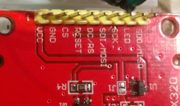
ILI9341 Pins
Programming the Display
When the ILI9341 first powers on it should show a uniform bright white color, but that’s just the backlight LEDs. The display will not try to show anything at all until it is initialized. Be aware that a broken display might still show a bright white screen when power is applied, but these modules are fairly sturdy. I’ve gone so far as to pry them apart and remove the backlights, and the panels worked even after being bluntly removed from the case.
This voids the warranty.
So short of taking a hammer to the screen, you shouldn’t be able to damage them too much by bumping them around or dropping them from a tabletop. Anyways, to start the display and put it into a state where it can draw things, we need to send it a series of startup commands. Like with the SSD1331 display, most commands are followed by one or more ‘option’ bytes, but unlike the SSD1331, those ‘option’ bytes should be sent with the D/C pin held high, not low. You can see all of the commands in the ILI9341 datasheet, but some commands appear to be undocumented, so it is a good idea to look at an existing library for a starting sequence that should work for most purposes.
Since Adafruit is awesome, they provide an ILI9341 library which is compatible with the Arduino IDE and devices which are supported by that – take a look at the .cpp file’s void Adafruit_ILI9341::begin(...) method. The command macros such as ILI9341_PWCTR1 are defined in the library’s .h file. The writeCommand method is similar to our hspi_cmd one, and spiWrite is used to write a byte over the SPI protocol, like our hspi_w8 method. So, our startup sequence can look something like this:
void ili9341_hspi_init(SPI_TypeDef *SPIx) {
  // (Display off)
  //hspi_cmd(SPIx, 0x28);

  // Issue a series of initialization commands from the
  // Adafruit library for a simple 'known good' test.
  // (TODO: Add named macro definitions for these hex values.)
  hspi_cmd(SPIx, 0xEF);
  hspi_w8(SPIx, 0x03);
  hspi_w8(SPIx, 0x80);
  hspi_w8(SPIx, 0x02);
  hspi_cmd(SPIx, 0xCF);
  hspi_w8(SPIx, 0x00);
  hspi_w8(SPIx, 0xC1);
  hspi_w8(SPIx, 0x30);
  hspi_cmd(SPIx, 0xED);
  hspi_w8(SPIx, 0x64);
  hspi_w8(SPIx, 0x03);
  hspi_w8(SPIx, 0x12);
  hspi_w8(SPIx, 0x81);
  hspi_cmd(SPIx, 0xE8);
  hspi_w8(SPIx, 0x85);
  hspi_w8(SPIx, 0x00);
  hspi_w8(SPIx, 0x78);
  hspi_cmd(SPIx, 0xCB);
  hspi_w8(SPIx, 0x39);
  hspi_w8(SPIx, 0x2C);
  hspi_w8(SPIx, 0x00);
  hspi_w8(SPIx, 0x34);
  hspi_w8(SPIx, 0x02);
  hspi_cmd(SPIx, 0xF7);
  hspi_w8(SPIx, 0x20);
  hspi_cmd(SPIx, 0xEA);
  hspi_w8(SPIx, 0x00);
  hspi_w8(SPIx, 0x00);
  // PWCTR1
  hspi_cmd(SPIx, 0xC0);
  hspi_w8(SPIx, 0x23);
  // PWCTR2
  hspi_cmd(SPIx, 0xC1);
  hspi_w8(SPIx, 0x10);
  // VMCTR1
  hspi_cmd(SPIx, 0xC5);
  hspi_w8(SPIx, 0x3E);
  hspi_w8(SPIx, 0x28);
  // VMCTR2
  hspi_cmd(SPIx, 0xC7);
  hspi_w8(SPIx, 0x86);
  // MADCTL
  hspi_cmd(SPIx, 0x36);
  hspi_w8(SPIx, 0x48);
  // VSCRSADD
  hspi_cmd(SPIx, 0x37);
  hspi_w8(SPIx, 0x00);
  // PIXFMT
  hspi_cmd(SPIx, 0x3A);
  hspi_w8(SPIx, 0x55);
  // FRMCTR1
  hspi_cmd(SPIx, 0xB1);
  hspi_w8(SPIx, 0x00);
  hspi_w8(SPIx, 0x18);
  // DFUNCTR
  hspi_cmd(SPIx, 0xB6);
  hspi_w8(SPIx, 0x08);
  hspi_w8(SPIx, 0x82);
  hspi_w8(SPIx, 0x27);
  hspi_cmd(SPIx, 0xF2);
  hspi_w8(SPIx, 0x00);
  // GAMMASET
  hspi_cmd(SPIx, 0x26);
  hspi_w8(SPIx, 0x01);
  // (Actual gamma settings)
  hspi_cmd(SPIx, 0xE0);
  hspi_w8(SPIx, 0x0F);
  hspi_w8(SPIx, 0x31);
  hspi_w8(SPIx, 0x2B);
  hspi_w8(SPIx, 0x0C);
  hspi_w8(SPIx, 0x0E);
  hspi_w8(SPIx, 0x08);
  hspi_w8(SPIx, 0x4E);
  hspi_w8(SPIx, 0xF1);
  hspi_w8(SPIx, 0x37);
  hspi_w8(SPIx, 0x07);
  hspi_w8(SPIx, 0x10);
  hspi_w8(SPIx, 0x03);
  hspi_w8(SPIx, 0x0E);
  hspi_w8(SPIx, 0x09);
  hspi_w8(SPIx, 0x00);
  hspi_cmd(SPIx, 0xE1);
  hspi_w8(SPIx, 0x00);
  hspi_w8(SPIx, 0x0E);
  hspi_w8(SPIx, 0x14);
  hspi_w8(SPIx, 0x03);
  hspi_w8(SPIx, 0x11);
  hspi_w8(SPIx, 0x07);
  hspi_w8(SPIx, 0x31);
  hspi_w8(SPIx, 0xC1);
  hspi_w8(SPIx, 0x48);
  hspi_w8(SPIx, 0x08);
  hspi_w8(SPIx, 0x0F);
  hspi_w8(SPIx, 0x0C);
  hspi_w8(SPIx, 0x31);
  hspi_w8(SPIx, 0x36);
  hspi_w8(SPIx, 0x0F);

  // Exit sleep mode.
  hspi_cmd(SPIx, 0x11);
  delay_cycles(2000000);
  // Display on.
  hspi_cmd(SPIx, 0x29);
  delay_cycles(2000000);
  // 'Normal' display mode.
  hspi_cmd(SPIx, 0x13);
}
After the display is reset and those commands are sent, the display should change to a flickering grey color. That tells you that the display is all set up and ready to go, but it has not received any pixel data yet so it is not showing any colors.
To draw to the display, we go through a similar process as we did with the SSD1331; send commands to say which rectangular area we want to draw to, then send one 16-bit color for each pixel in that rectangular area.
To refresh the entire 240 x 320 display, we can set the drawing area to be between (0, 0) and (239, 319) and then draw 320 * 240 = 76,800 pixels of data. That’s a lot of data – even at one bit per pixel, the small chips used in this example would not have enough RAM to store a full framebuffer. You’d need over 600KB of RAM to store a full 16 bits of color per pixel, so we’ll only draw some solid colors in this tutorial.
That sequence of commands looks like this, including a main loop:
// Main loop - empty the screen as a test.
int tft_iter = 0;
int tft_on = 0;
// Set column range.
hspi_cmd(SPI1, 0x2A);
hspi_w16(SPI1, 0x0000);
hspi_w16(SPI1, (uint16_t)(239));
// Set row range.
hspi_cmd(SPI1, 0x2B);
hspi_w16(SPI1, 0x0000);
hspi_w16(SPI1, (uint16_t)(319));
// Set 'write to RAM'
hspi_cmd(SPI1, 0x2C);
while (1) {
  // Write 320 * 240 pixels.
  for (tft_iter = 0; tft_iter < (320*240); ++tft_iter) {
    // Write a 16-bit color.
    if (tft_on) {
      hspi_w16(SPI1, 0xF800);
    }
    else {
      hspi_w16(SPI1, 0x001F);
    }
  }
  tft_on = !tft_on;
}
And that’s all there is to it! As the program runs, your display should cycle between a red and blue color as fast as the chip can send data. This could be made even faster by using hardware interrupts and/or DMA transfers, but that is a topic for a future tutorial.
Conclusions
The ILI9341 is a good display driver to know how to use. Screens using it come in sizes from about 2.2″ – 3.2″ with a resolution of 240 x 320 pixels, and they are very affordable. Their contrast is not as good as the SSD1331 OLED displays, but they get you a lot more pixels on a hobbyist’s budget.
So all in all, they’re nice choices for small applications which need an easy-to-read display. I’ve seen them used in devices ranging from handheld oscilloscopes to CNC machines. Chime in if you wind up making anything with one!
As usual, a project demonstrating this code is available on Github.


Yesenia Poppleton
December 1, 2018 at 6:28 pm
When I originally commented I clicked the “Notify me when new comments are added” checkbox and now each time a comment is added I get three emails with the same comment. Is there any way you can remove people from that service? Appreciate it!
Vivonomicon
December 2, 2018 at 2:50 pm
Hm, sorry about that – I’m pretty new to this whole ‘blog’ thing. I hadn’t even realized there was a comment subscription option, but since you mentioned it I installed a plugin to hopefully make those more user-friendly.
I couldn’t find any existing subscriptions from within that plugin, but I think any emails that go out should have an unsubscribe or ‘manage subscriptions’ link which you can use. I also turned on an option to send a confirmation email before enabling these subscriptions, but let me know if you keep seeing issues.
Sorry!
kratatau
February 11, 2019 at 2:24 pm
Hi Vivonomicon,
Thank You for this excellent blog. Although I’m just a beginner, thanks to your explanations I was able to start with STM32 and moved your code to Bluepill (F103). Now, after a little tuning my ILI9341 works like a charm. Please continue with your enlightenment.
Greetings from Czechia.
kratatau
Vivonomicon
February 12, 2019 at 7:06 pm
I’m glad to hear this was helpful – the F103 cores definitely seem like reliable workhorses. Good luck, I hope your projects work well!
Massimo M.; Italy
February 12, 2019 at 2:54 am
I adapted this to a F072RB. Thanks a lot for yur help!
Now I’m trying to use DMA and a scalable fonts/other utilities for this display. Unfortunately I find too much example but extremely confused…
If someone have a good example like this why don’t share the link?
Vivonomicon
February 12, 2019 at 7:02 pm
That’s great to hear, congratulations! I would also like to learn more about DMA on the STM32, but unfortunately I haven’t had time to look into it yet. You might look at the examples in the ‘STCube’ package distributed by ST, though, and I have also seen some blog posts about using DMA to drive ‘neopixel’ LEDs, like this one:
http://www.martinhubacek.cz/arm/improved-stm32-ws2812b-library
It seems like that might be a good place to start, especially since many of those examples also use the SPI peripheral.
David
March 5, 2019 at 10:19 am
Hi, could please help me how do i display text or variables on screen?
Vivonomicon
March 30, 2019 at 12:35 pm
For that sort of thing, you would probably want to use an existing library – most of them will make a ‘framebuffer’ object which is just a big array with the current pixel colors. For a 16-bit TFT, you’d probably make it an array of `uint16_t`s. To refresh the display, you send the whole framebuffer one color at a time. And to ‘draw’ to it, you change the color values in the array.
It looks like most libraries implement helper methods for drawing shapes, text, etc. For an example that is designed for monochrome displays, maybe check out U8G2?
https://github.com/olikraus/u8g2
I was thinking of doing that in this tutorial, but a framebuffer for 320×240 pixels at 16 bits per pixel is 150KB, and not many cheap microcontrollers have that much RAM.
kratatau
April 10, 2019 at 5:11 am
Hi, I did it pretty much the way Vivonomicon described. You just need a ASCII font in the form of array bytes, where each byte describes a column. Then say 5 of these columns alongside make one character, – bits ‘1’ with different color than ‘0’.
You can even magnify the font with a simple routine.
I used just a part of ASCII table to save the memory.
If you are interested, I can send you my code
Yitong Dai
March 18, 2019 at 7:19 pm
Really appreciate the tutorial. I am trying to use this display to implement a simple game. I wonder if SPI bandwidth will be the bottleneck. Also I try to modify Adafruit graphics library in order to use it wiht my STM32 board. One thing I noticed is that in Adafruit graphics library, startWrite() and endWrite() will be called before sending color data to the display. I know it has something to do with SPI, but I can’t find the corresponding part in your tutorial. I am guessing in your tutorial you just use one transaction? If yes, is it necessary to have multiple transactions if I want to make a game?
Vivonomicon
March 30, 2019 at 12:42 pm
It might be, but I think that you can use clock rates as fast as 20-40MHz. There are also versions of these displays which support 8, 16, and 18-bit parallel interfaces if that is too slow; they’re described in the datasheet, but I haven’t figured out how they work yet.
I’m not sure what the ‘start/endWrite’ methods do without looking at the library, but SPI devices usually have a ‘Chip Select’ (CS) pin which tells the device when it is being addressed. You can have multiple devices share the same clock/data lines, and any chips without their CS pins asserted will ignore the data. With most devices, pulling the CS pin to V++ will put the device to ‘sleep’, while pulling it to Ground will activate it.
A lot of devices have the CS pin connected to V++ through a pull-up resistor, and some devices will misbehave if it is permanently pulled to Ground, so that can be a good place to look if you have trouble communicating with the display over SPI. For this tutorial, I think that ‘startWrite’ is probably the same as pulling the CS pin to Ground, while ‘endWrite’ equates to pulling it high.
Good luck, I hope your game turns out well!
Yitong Dai
June 23, 2019 at 3:36 pm
This is what I eventually end up with (https://r9dyt.weebly.com/galaga.html). Your tutorial really helps me a lot, thank you for sharing it and keep it up!
Vivonomicon
June 26, 2019 at 7:45 am
That’s great to hear, congratulations! It looks like an impressive project, nice job with the fast refresh rate.
Yitong Dai
March 19, 2019 at 8:45 pm
I wonder if SPI bandwidth will be the bottleneck if I want to use what’s cover in the tutorial to have some interactive graphics.
Maunik Patel
March 26, 2019 at 12:16 am
Hi,
Thanks for this very helpful and well-described post.
I am trying to interface ILI9341V display with STM32F030C6, using 3-wire, 9-bit, Software SPI.
Here, I am not using D/C pin. Instead, I am appending an additional D/C ‘bit’ before sending Data/command.
The display initialization process is the same as the one you mentioned in this post.
I cross-checked SCK, SDA, and CS pins using CRO and seems like every pin is working fine.
Still, am seeing a pure white display, that doesn’t flicker after initialization as you have mentioned in this post.
Can you help me to solve this unknown issue?
Vivonomicon
March 30, 2019 at 12:46 pm
Hm, I haven’t used the 3-wire SPI mode before, but looking at the datasheet it looks like the D/C bit should be the first bit sent, followed by the byte MSB->LSB. Are you sure that it’s being sent in that order? Also, have you confirmed that the display works with an existing library to rule out hardware or power supply issues?
Pythno
April 7, 2019 at 1:08 pm
Thank you very much for the writeup. I was trying today setting up the display on my “blue pill” but failed. So I was googling and found this. A few questions: The AFR and MODE Registers are not available for me. Also, the datasheet for the STM32F103c8x doesn’t mention those registers at all. Do you know why? I have a book about the STM32 and it also uses MODE and AFR registers. A bit lost there 😉
Vivonomicon
April 8, 2019 at 11:38 am
Different ‘major versions’ of STM32s can have different peripheral layouts. Usually the registers and commands look fairly similar, but the “F1” series which the STM32F103 belongs to is one of the older lines, so a lot of its peripherals look different from the newer chips.
The GPIO peripheral is one example – take a look at the ‘GPIOs and AFIOs’ chapter (currently chapter 9) in the reference manual (PDF). The register descriptions are at the end of the chapter, and you can see that each GPIO bank has two ‘port configuration registers’ called ‘CRL’ and ‘CRH’. ‘CRL’ controls pins 0-7, and ‘CRH’ controls pins 8-15.
You can read the register descriptions for more information, but basically each pin gets a 2-bit ‘MODE’ setting and a 2-bit ‘CNF’ setting. The ‘MODE’ bits are similar to the ‘MODER’ and ‘OSPEEDR’ registers, in that they choose between input/output mode, and select the maximum speed for output mode. The ‘CNF’ bits choose between push-pull/open-drain/alternate-function modes if the pin is in output mode, or analog/floating/pull-up/pull-down settings if it is in input mode.
Also, if you configure a pin as ‘input with pull-up or pull-down’, I think that you might need to write a ‘1’ or ‘0’ to the pin to set the pulling direction.
And I don’t think I’ve looked too closely at the SPI peripheral on the STM32F1 series, but it might also look different from what I described in these posts – sorry about that, but good luck!
pythong
April 10, 2019 at 6:00 pm
thanks! I got it to work to be initialized, apparently. I get the grayish screen. It seems like alternating darker lines from top to bottom. However, I cannot get pixels on the screen. I tried several things. The byte order didn’t seem to do anything. By the way…. why don’t you do the CS before you transmit data? It seems to miss in your code snippets?
Vivonomicon
May 13, 2019 at 9:10 am
Well, in my experience that sort of grey screen with alternating bright/dark lines usually means that the display was initialized properly, but I’ve never used the 3-wire SPI mode before. I think it might use an extra bit instead of the ‘Data/Command’ pin, so maybe it could be interpreting your pixel data as commands if that isn’t being set correctly? Sorry, I’m not sure.
And the CS pin should be pulled low when a SPI transaction is happening, like with the software SPI tutorial – I think that should be in the full example code, but I might have omitted it in the snippets, sorry.
Timothy
June 4, 2020 at 7:56 pm
Great Job,
Can this code be adapted for TFT with the SSD1963 drivers?
Vivonomicon
June 6, 2020 at 11:21 am
I would guess that similar commands would work, since a lot of these display drivers seem to share and re-use them.
But unfortunately, it looks like the SSD1963 controls higher-resolution displays, and if I’m reading their datasheet right, they don’t support the SPI interface which I used here. It’s probably not fast enough to get a good refresh rate.
So you’d need to write different ‘write command/data’ methods which use the 24-bit parallel interface. Some STM32s have a ‘MIPI DSI’ peripheral for communicating with that sort of parallel display, but they’re usually larger or more expensive like the STM32F767, and I haven’t tried using one yet.