
RISC-V Baremetal Examples
Festive Cross-Platform Holiday Lights
Across the globe, people seem to enjoy decorating their homes, communities, and outdoor spaces with lights and ornaments during the winter holidays. Maybe it helps with the depressingly early sunsets for those of us who don’t live near the equator. Anyways, I thought it’d be fun to make some ornaments with multi-color addressable LEDs last year, and I figured I’d write about what worked and what didn’t.
I didn’t have many microcontrollers at the time because I was visiting family for the holidays, so I ended up coding the lighting patterns for a cheap little STM32F103 “black pill” board which was in the bottom of my backpack. And it’s a convenient coincidence that I just started learning about the very similar GD32VF103 chips with their fancy RISC-V CPUs and nearly-identical peripheral layout, so this also seems like a good opportunity to write about how to cross-compile the same code for two different CPU architectures.

Pretty holiday stars! “Frosted white” acrylic sheets aren’t the best way to diffuse light, but they are cheap and easy to work with.
This was a fun and festive project, and it might not be a bad way to introduce people to embedded development since there are so many ways to drive these ubiquitous “NeoPixel” LEDs. Sorry that this post is a little bit late for the winter holidays – I’ve been traveling for the past few months – but maybe it’ll get you thinking about next year 🙂
I’ll talk about how I assembled the stars and what I might do differently next time, then I’ll review how to light them up with an STM32F103, and how to adapt that code for a GD32VF103. But you could also use a MicroPython or Arduino board to set the LED colors if you don’t want to muck around with peripheral registers.
Bare-metal RISC-V Development with the GD32VF103CB
For the past few years, there has been growing excitement about the RISC-V instruction set architecture. It is an appealing architecture because it is open-source (which can mean royalty-free), and flexible enough to be configured for everything from small power-efficient microcontrollers to fast and complex application processors. In this post, we’ll learn how to write a simple program for a GigaDevice GD32VF103 chip, which leans towards the “small and power-efficient” end of the spectrum.
There have already been a handful of opportunities for hobbyists to use RISC-V hardware in their projects, such as the SiFive “Freedom” chips and Kendryte K210 modules. But the SiFive boards are expensive and (up until this point) produced in limited quantities, and most of the cheaper options have been narrowly focused on niches like machine learning or IoT applications. The GD32VF103 is still fairly new, and while there’s no guarantee that it won’t end up in history’s dustbin of one-off chips, it is an affordable general-purpose chip with a few tricks up its sleeve which should make it a nice learning platform.
First, it is easy to buy a handful of boards which use these chips: you can buy “Longan Nano” boards for about $5 from Seeed Studios, and they also sell compatible USB/JTAG debugging dongles. The GD32V chips have decent support for flashing and debugging, with a fork of DFU-utils to upload code over USB and a fork of OpenOCD to open a debugging connection to the chip. I hope that support for these chips is eventually integrated into the core projects, but in these early days, you’ll have to build patched versions.
There is also a HAL repository with C code to help you access the chip’s peripherals, but one more reason why this chip is an appealing learning platform is that its peripherals work very similarly to those found in the venerable STM32F1 family of microcontrollers. So while you can use the vendor-provided HAL, you can also get a head start on writing your own drivers by migrating code written for older STM32F103 chips, even though they have a different CPU architecture! How cool is that? 🙂
If any of that sounds interesting, keep reading – we’ll use the “Longan Nano” board that I mentioned above as the target hardware for this blog post, but the first few sections should apply to most boards that use a GD32VF103 chip. We’ll start with the basic boot/startup code which is needed to get to the ‘main’ method in a C program, then we’ll configure a few GPIO pins to toggle the on-board RGB LEDs. After that, we’ll set up a hardware interrupt to generate timed delays using the CPU’s timer peripheral (similar to ARM’s SysTick). Finally, we’ll set up DMA with the SPI peripheral to draw to the board’s 160×80-pixel display.
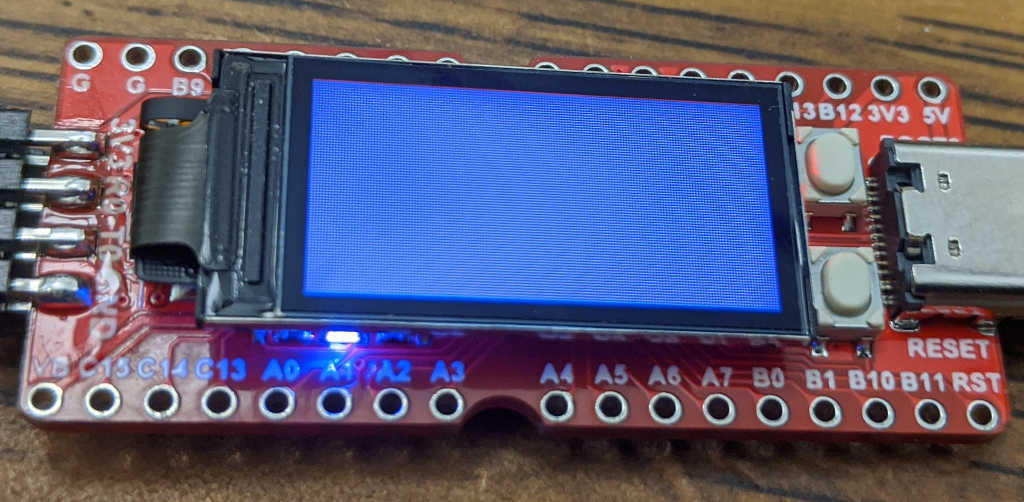
We’ll write some basic startup code for the chip, then set up its GPIO and SPI peripherals to light up the on-board LEDs and display.