
Across the globe, people seem to enjoy decorating their homes, communities, and outdoor spaces with lights and ornaments during the winter holidays. Maybe it helps with the depressingly early sunsets for those of us who don’t live near the equator. Anyways, I thought it’d be fun to make some ornaments with multi-color addressable LEDs last year, and I figured I’d write about what worked and what didn’t.
I didn’t have many microcontrollers at the time because I was visiting family for the holidays, so I ended up coding the lighting patterns for a cheap little STM32F103 “black pill” board which was in the bottom of my backpack. And it’s a convenient coincidence that I just started learning about the very similar GD32VF103 chips with their fancy RISC-V CPUs and nearly-identical peripheral layout, so this also seems like a good opportunity to write about how to cross-compile the same code for two different CPU architectures.

Pretty holiday stars! “Frosted white” acrylic sheets aren’t the best way to diffuse light, but they are cheap and easy to work with.
This was a fun and festive project, and it might not be a bad way to introduce people to embedded development since there are so many ways to drive these ubiquitous “NeoPixel” LEDs. Sorry that this post is a little bit late for the winter holidays – I’ve been traveling for the past few months – but maybe it’ll get you thinking about next year 🙂
I’ll talk about how I assembled the stars and what I might do differently next time, then I’ll review how to light them up with an STM32F103, and how to adapt that code for a GD32VF103. But you could also use a MicroPython or Arduino board to set the LED colors if you don’t want to muck around with peripheral registers.
We’re All in the Gutter, but Some of Us are Looking at the Stars
I chose a star shape to make ornaments out of, because it is generally festive and it tessellates well. But you could use any sort of silhouette depending on whatever holiday is coming up at the time. Maybe a pumpkin with orange lighting for Halloween, a four-leaf clover with green lighting for St. Patrick’s day, a multi-color splat for Holi, the possibilities are endless. The parts that I used were:
- Laser-cut acrylic “faces” (2 per star)
- Neoprene foam weatherproofing tape (1/2″ – 1″ wide, to preference)
- Addressable LED strips (
WS2812BorSK6812, 30 LEDs / meter) - 3-pin LED connectors (1 pair per star)
- 5V power supply (~1W for every 3-5 LEDs)
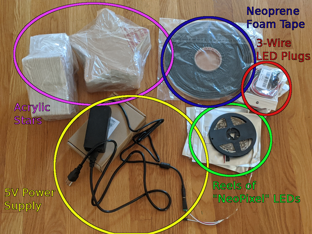
Holiday star parts. Not pictured: a microcontroller to send colors to the LEDs.
To make the acrylic faces, you can use a laser cutter if you have access to one. If you don’t, you can also ask local plastic shops if they’ll do a small run of simple cuts. I was able to get a few dozen stars cut out by emailing a local store which sold acrylic sheets; they told me their minimum order size, I sent them an SVG file with the patterns to cut, and it shipped after a few days. That was the easiest option since I was traveling and getting ready to move, but if you live near a large city, it would probably be cheaper to join a local makerspace and do your own cuts.
Once I had the stars, I measured around the shape’s outline and cut lengths of foam tape and LED ribbon to match. Then I soldered some 3-pin LED strip connectors onto the ends of each length, and stuck the LED strips to the foam tape. I’m not sure exactly what these connectors are called since I just ordered a few dozen “3-pin LED connectors” off of Amazon, but it shouldn’t matter what kind you use as long as they all match.
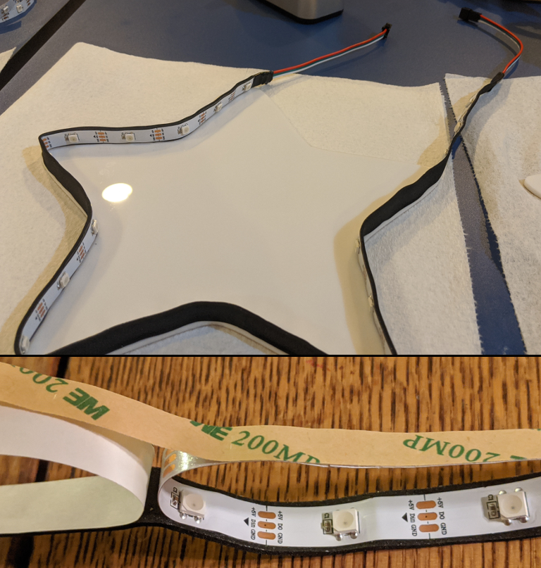
Making “LED foam tape” to outline and separate the star faces.
To assemble the ornaments, I sandwiched strips of neoprene foam weatherproofing tape between the two star-shaped faces which were cut out of 3mm-thick “Chemcast” acrylic. It was easier to stick the outline onto one face before attaching the second one, like in the picture above. The 3-wire plugs protrude from the gap where the ends of the foam outline meet, and hot-melt glue fills that gap and provides strain relief. I also used cyanoacrylate (“super glue”) to supplement the foam tape adhesive which holds the acrylic and tape together.
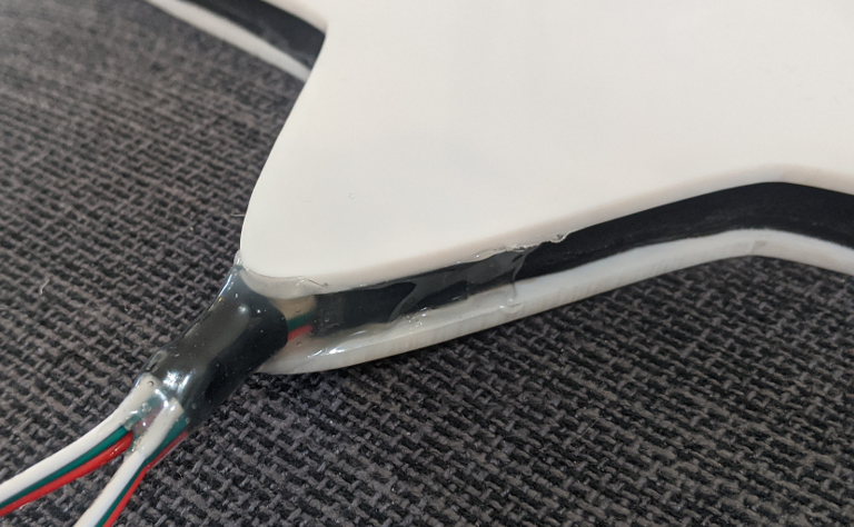
Hot glue can fix anything.
I also tried attaching thicker foam tape “around” the edges of the acrylic instead of placing a thin spacer “between” the faces. This was easier to assemble, but I noticed that the adhesive didn’t hold as well if I accidentally stretched or compressed the tape too much when I “wrapped” it around the stars:
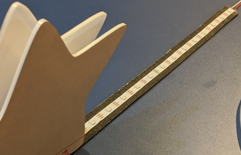
Wrapping thicker foam tape around the star is easier, but it’s harder to get the adhesive to take hold.
So I’d say it’s a bit of a toss-up. I do like the look of the “wrap-around” foam better because you can see a distinct outline around the star, but you get the same effect either way. If I had to do it again, I’d get a more viscous cyanoacrylate glue to seal the edges where the acrylic meets the foam tape. It’d probably help with stability and weatherproofing, although I did take a couple of these out in the rain for a few hours with a battery and they seemed fine. I’d also get longer LED connectors; the wire connectors were so short that the stars were touching when I daisy-chained them together, so I had to make extension cables out of spare connectors to actually hang them up.
STM32F103 Software: Programming Animations with SPI and DMA
This sort of application is where the cheap-and-cheerful STM32F103C8 “blue pill” and “black pill” boards really shine. Since they cost less than a cup of coffee, you can toss them into one-off projects like this without worrying about re-using the board later. In this case, I soldered one of the 3-wire LED connectors directly to the board instead of attaching pin headers:
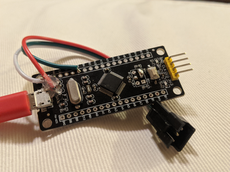
STM32F103 LED driver. The “B5” pin connects to the SPI1 peripheral’s “MOSI” signal. Notice that the “BOOT0” signal is also shorted to ground with a solder blob.
Unfortunately, the pictured board doesn’t have a 5V output pin. I ran into the same problem when I wanted to get 5V out of an “Icestick” FPGA board, and I used the same solution here: solder a wire to one of the voltage regulator’s input capacitors, and add some hot glue to keep the wire from snapping off.
Peripheral Setup
I didn’t have much time to put this project together, so I copied a bunch of the code from earlier projects and I didn’t write very many lighting patterns. The LED colors are sent through a continuous DMA transfer, with a SPI peripheral generating the precisely-timed 1 and 0 data pulses which the LEDs expect. I wrote more about how this works in part 3 of my post about the STM32 DMA peripherals, and the same configuration works with this STM32F103 chip.
Unfortunately, the first step was to slow down the core clock speed to 48MHz instead of the maximum 72MHz. It’s important to get the timings right; you can read my DMA tutorial for more information on why, but I needed a 6MHz baud rate for the SPI peripheral, and it only lets you divide by an exponent of 2. So 48MHz / 8 = 6MHz, but 72MHz doesn’t work.
Another downside of this approach is that it uses one byte of memory for every bit of color data, which is not very efficient. You could probably find a combination of prescalers and clock speeds to do a better job, but I was in a hurry and I didn’t have an oscilloscope to debug timing issues. So, here’s an example of how to set up the PLL for a 48MHz clock speed:
// Set 1 wait state in flash and enable the prefetch buffer.
FLASH->ACR &= ~(FLASH_ACR_LATENCY);
FLASH->ACR |=  (0x1 << FLASH_ACR_LATENCY_Pos |
                FLASH_ACR_PRFTBE);
// Enable the 8MHz external crystal oscillator.
RCC->CR    |=  (RCC_CR_HSEON);
while (!(RCC->CR & RCC_CR_HSERDY)) {};
// Set the HSE oscillator as the system clock source.
RCC->CFGR  &= ~(RCC_CFGR_SW);
RCC->CFGR  |=  (RCC_CFGR_SW_HSE);
// Set the PLL multiplication factor to 6, for 8*6=48MHz.
RCC->CFGR  &= ~(RCC_CFGR_PLLMULL);
RCC->CFGR  |=  (RCC_CFGR_PLLMULL6);
// Set the PLL to use the HSE oscillator.
RCC->CFGR  |=  (RCC_CFGR_PLLSRC);
// Enable the PLL.
RCC->CR    |=  (RCC_CR_PLLON);
while (!(RCC->CR & RCC_CR_PLLRDY)) {};
// Set the PLL as the system clock source.
RCC->CFGR  &= ~(RCC_CFGR_SW);
RCC->CFGR  |=  (RCC_CFGR_SW_PLL);
// The system clock is now 48MHz.
SystemCoreClock = 48000000;
You’ll also need to enable the peripheral clocks, set up pin B5 as a medium-speed alternate-function push-pull output, and set the SPI1 “remap” bit so that the MOSI (data output) signal goes to pin B5 instead of pin A7:
// Enable peripheral clocks: AFIO, GPIOA/B/C, DMA1, SPI1.
RCC->APB2ENR  |=  ( RCC_APB2ENR_AFIOEN |
                    RCC_APB2ENR_IOPAEN |
                    RCC_APB2ENR_IOPBEN |
                    RCC_APB2ENR_IOPCEN |
                    RCC_APB2ENR_SPI1EN );
RCC->AHBENR   |=  ( RCC_AHBENR_DMA1EN );

// PB5 SPI1 MOSI pin setup: push-pull output, alt. func., mid-speed.
GPIOB->CRL &= ~( 0xF << 20 );
GPIOB->CRL |=  ( 0x9 << 20 );
AFIO->MAPR |=  ( AFIO_MAPR_SPI1_REMAP );
Remember that you can check a chip’s datasheet to see which pins connect to which peripheral signals. You’ll also need a way to keep time if you want to create animations, so don’t forget to set up the SysTick peripheral and a “millisecond delay” function:
// SysTick counter definition.
volatile uint32_t systick = 0;

// Delay for a specified number of milliseconds.
void delay_ms( uint32_t ms ) {
  // Calculate the tick value when the system should stop delaying.
  uint32_t next = systick + ms;

  // Wait until the system reaches that tick value.
  // Use the 'wait for interrupt' instruction to save power.
  while ( systick < next ) { __asm__( "WFI" ); }
}

// (... somewhere in your main method after the core clock speed is set ...)
    // Setup the SysTick peripheral to 1ms ticks.
    SysTick_Config( SystemCoreClock / 1000 );
Finally, here’s how I set up the SPI / DMA peripherals to continuously send a colors buffer to the LED string:
/* (Outside of your main method) */
// Number of LEDs per star.
#define STAR_LEDS ( 23 )
// Number of stars in the string.
#define NUM_STARS ( 7 )
// LED colors buffer. (GRB*8)
#define NUM_COLOR_BYTES ( NUM_STARS * STAR_LEDS * 3 )
#define NUM_COLOR_BITS  ( NUM_COLOR_BYTES * 8 )
// (Add 64 cycles for a latching sequence)
#define COLOR_ARRAY_LEN ( NUM_COLOR_BITS + 64 )
// Memory buffer holding the LED colors. The DMA channel will use
// this buffer as its 'source address' for data to send over SPI.
uint8_t colors[ COLOR_ARRAY_LEN ];


/* (Inside of your main method) */
// DMA setup: on STM32F103s, SPI1_TX is mapped to DMA1, Channel 3.
// - Memory-to-peripheral mode.
// - Circular mode enabled for continuous transfer.
// - Increment source ptr, don't increment destination ptr.
// - 8-bit transfer length.
// - High-priority. Not that priority matters; it's the only one.
DMA1_Channel3->CCR &= ~( DMA_CCR_MEM2MEM |
                         DMA_CCR_PL |
                         DMA_CCR_MSIZE |
                         DMA_CCR_PSIZE |
                         DMA_CCR_PINC |
                         DMA_CCR_EN );
DMA1_Channel3->CCR |=  ( ( 0x2 << DMA_CCR_PL_Pos ) |
                         DMA_CCR_MINC |
                         DMA_CCR_CIRC |
                         DMA_CCR_DIR );
// Set source memory address to the 'colors' array.
DMA1_Channel3->CMAR  = ( uint32_t )&( colors );
// Set destination peripheral address to the SPI1 data register.
DMA1_Channel3->CPAR  = ( uint32_t )&( SPI1->DR );
// Set the number of color bits. The maximum is 64K, but it's safe
// to assume we will be in that range since there's only 20K of RAM.
DMA1_Channel3->CNDTR = ( uint16_t )( COLOR_ARRAY_LEN );
// Enable the DMA channel.
DMA1_Channel3->CCR  |= ( DMA_CCR_EN );
// SPI1 setup: host mode, /8 baud rate division, sw cs pin control,
// TX DMA enabled, 8-bit frames, msb-first, enable the peripheral.
// Some of those settings are the default state after a reset.
SPI1->CR2  |=  ( SPI_CR2_TXDMAEN );
SPI1->CR1  |=  ( SPI_CR1_SSM |
                 SPI_CR1_SSI |
                 SPI_CR1_MSTR |
                 SPI_CR1_SPE |
                 0x2 << SPI_CR1_BR_Pos );
And remember, you can find a full example project with all of this code and supporting build files on GitHub; I’m only calling out the important parts to explain how the application works. For more context on how the project is organized, see my earlier STM32 tutorials.
LED Patterns
Once all of that setup is complete, any colors that you set in the colors array will quickly be reflected as actual colors on your LED strip. But since the SPI peripheral is sending one byte of data to generate the timings for one bit of color data, you’ll also need a helper function to translate “Red / Green / Blue” color values into a format that the LEDs can recognize:
// SPI timing values for color bits. (One SPI byte = one color bit)
#define WS2812_ON  ( 0xFC )
#define WS2812_OFF ( 0xC0 )

// Set a 24-byte GRB pixel color from 3 RGB bytes.
void set_px_rgb( uint8_t* px, uint8_t r, uint8_t g, uint8_t b ) {
  // Green color.
  for ( int i = 0; i < 8; ++i ) {
    if ( g & ( 1 << ( 7 - i ) ) ) { px[ i ] = WS2812_ON; }
    else { px[ i ] = WS2812_OFF; }
  }
  // Red color.
  for ( int i = 0; i < 8; ++i ) {
    if ( r & ( 1 << ( 7 - i ) ) ) { px[ i + 8 ] = WS2812_ON; }
    else { px[ i + 8 ] = WS2812_OFF; }
  }
  // Blue color.
  for ( int i = 0; i < 8; ++i ) {
    if ( b & ( 1 << ( 7 - i ) ) ) { px[ i + 16 ] = WS2812_ON; }
    else { px[ i + 16 ] = WS2812_OFF; }
  }
}
This is not very memory-efficient, but (mis)using the SPI peripheral like this is sort of a hack anyways. And since I was rushed to finish this, the code which drives these LED patterns is not exactly clean or easy to read. Sorry about that, but I’ll still try to explain how it works.
Now that you can set individual colors in a string of these LEDs, how do you process individual animations for each star? If you write animations which process the entire chain of LEDs at once, it can be difficult to create patterns which treat each star as its own ‘ring’ of colors. One way to process each star separately is to split the colors array into a smaller array of star_t structs which you can define in a header file (such as patterns.h in the reference repository):
/* (These definitions were also mentioned in the SPI / DMA configuration code) */
// Number of LEDs per star.
#define STAR_LEDS ( 23 )
// Number of stars in the string.
#define NUM_STARS ( 7 )
// Number of bytes required to hold colors for all of the stars.
#define NUM_COLOR_BYTES ( NUM_STARS * STAR_LEDS * 3 )
#define NUM_COLOR_BITS  ( NUM_COLOR_BYTES * 8 )
// (Add 64 bytes at the end to "latch" LED colors)
#define COLOR_ARRAY_LEN ( NUM_COLOR_BITS + 64 )
// Memory buffer holding the LED colors.
uint8_t colors[ COLOR_ARRAY_LEN ];

// Enumeration for lighting patterns.
typedef enum {
  ls_min = 0,
  rainbow_lp = 0,
  rainbow,
  breathe_r,
  breathe_g,
  breathe_b,
  ls_max,
} light_steps;
// Star struct.
typedef struct {
  uint8_t* my_colors;
  int cur_pattern;
  int last_step;
  int next_step;
} star_t;

// Array of star structs.
star_t stars[ NUM_STARS ];
In my case, I have a string of 7 stars with 23 LEDs in each star. That’s just how the sizes worked out, and I didn’t want to connect more than about 150 LEDs to my 5V power supply. Remember, these LEDs can each draw as much as 50mA (0.25W) depending on the color and brightness.
Each “star” object has a my_colors pointer which points to the location in the main colors array where that star’s LED colors start, and a cur_pattern value which defines the current animation to play from the light_steps enumeration.
The last_step / next_step values contain time values: last_step indicates when the last pattern ended, and next_step indicates when the next pattern should begin. Animations can calculate their “progress” by comparing the current systick value to these _step attributes.
To play the animations, I wrote a step_star function which sets an individual star’s colors based on how far its current animation has progressed. Then I called that function on each star_t object in an infinite loop, with a 50ms delay between each group of calls. Adjusting the delay length adjusts how smoothly the animations play; it isn’t elegant, but it works:
// Send new colors and blink the on-board LED at an interval.
while ( 1 ) {
  // Delay briefly
  delay_ms( 50 );
  // Step the lighting display.
  for ( int i = 0; i < NUM_STARS; ++i ) {
    step_star( &( stars[ i ] ) );
  }
}
That just leaves the step_star function itself. It starts by calculating the current animation’s progress and switching to a new animation if necessary, and then it sets individual LED colors based on the current animation’s progress. I won’t copy the whole thing here to avoid repetition, but remember that you can find a full example project on GitHub:
// Step one star's lighting pattern.
void step_star( star_t* star ) {
  // Use the same definition of 'now' for the whole function.
  int this_tick = systick;
  // Move to the next pattern if necessary.
  if ( star->next_step < this_tick ) {
    star->last_step = this_tick;
    star->next_step = this_tick + STEP_DUR;
    ++star->cur_pattern;
    if ( star->cur_pattern == ls_max ) { star->cur_pattern = ls_min; }
  }

  // Update colors to match the current pattern.
  // The downside of using an ancient STM32F1 chip is that it
  // lacks floating-point hardware, so integer math is much faster.
  uint8_t step_brightness = ( ( this_tick - star->last_step ) * 0xFF ) / ( STEP_DUR / 2 );
  if ( ( this_tick - star->last_step ) > ( STEP_DUR / 2 ) ) {
    step_brightness = 0xFF - ( step_brightness - 0xFF );
  }
  if ( star->cur_pattern == breathe_r ) {
    for ( int i = 0; i < STAR_LEDS; ++i )  {
      set_px_rgb( &( star->my_colors[ i * 24 ] ), step_brightness, 0x00, 0x00 );
    }
  }
  else if ( star->cur_pattern == breathe_g ) {
    for ( int i = 0; i < STAR_LEDS; ++i )  {
      set_px_rgb( &( star->my_colors[ i * 24 ] ), 0x00, step_brightness, 0x00 );
    }
  }
  // (more patterns...)
  else {
    for ( int i = 0; i < STAR_LEDS; ++i )  {
      set_px_rgb( &( star->my_colors[ i * 24 ] ), 0x00, 0x00, 0x00 );
    }
  }
}
The “breathing color” patterns are about as simple as you can get: you calculate a brightness value based on how far along the animation is, and set all of the star’s LEDs to one color with that brightness.
The “rainbow” patterns are a bit more complicated, but you can find the code in the GitHub project. And honestly, I was rushed enough that I don’t feel very happy with my rainbow_cycle function. It works, but I didn’t copy it here because I bet you could write something better after a few minutes of Googling 🙂
RISC-V Cross-Compilation: Building for a GD32VF103
With a working STM32F103 application, I thought it would be fun to add an option to build for a newer GD32VF103 RISC-V chip. After all, the peripherals are almost identical, and it would be possible to use a faster 96MHz clock speed to generate the 6MHz SPI baud rate thanks to the higher speed limit of 108MHz.
But to do that, we need to update the project’s Makefile, add the RISC-V device header files, and adapt the program to account for CPU-specific peripherals such as the interrupt controller. I recently wrote a tutorial about how to get started with bare-metal GD32VF103 development; check that out for information about how to install the RISC-V GNU toolchain and write simple applications for those chips.
Makefile Changes
Even if the code is mostly identical, the build commands for STM32 and GD32V chips are different because of their different CPU architectures. I usually manage this sort of thing by adding an MCU variable to the Makefile which defines what sort of microcontroller is being targeted. The Makefile can set values like CFLAGS differently based on the target hardware, and in this case we can also have it use a different compiler.
Here’s an example Makefile which can target two chips. Since the MCU value is set with ?= instead of =, you can override it from the command line with make -DMCU=[...]:
TARGET = main

# Default target chip.
#MCU ?= STM32F103x8
#MCU ?= STM32F103xB
MCU ?= GD32VF103xB

# Define target chip information.
ifeq ($(MCU), STM32F103x8)
  MCU_FILES = STM32F103x8
  ST_MCU_DEF = STM32F103xB
  MCU_TYPE = STM32
else ifeq ($(MCU), STM32F103xB)
  MCU_FILES = STM32F103xB
  ST_MCU_DEF = STM32F103xB
  MCU_TYPE = STM32
else ifeq ($(MCU), GD32VF103xB)
  MCU_FILES = GD32VF103xB
  MCU_TYPE = GD32V
endif

ifeq ($(MCU_TYPE), STM32)
  # Assembly and C flags.
  ASFLAGS += -mcpu=cortex-m3
  ASFLAGS += -mthumb
  CFLAGS  += -mcpu=cortex-m3
  CFLAGS  += -mthumb
  CFLAGS  += -msoft-float
  CFLAGS  += -mfloat-abi=soft
  CFLAGS += -D$(ST_MCU_DEF)
  LFLAGS += -mcpu=cortex-m3
  LFLAGS += -mthumb
  LFLAGS += -msoft-float
  LFLAGS += -mfloat-abi=soft
  # Toolchain definitions (ARM Cortex-M bare metal defaults)
  CC = arm-none-eabi-gcc
  OC = arm-none-eabi-objcopy
  OS = arm-none-eabi-size
else ifeq ($(MCU_TYPE), GD32V)
  # Assembly, C, and linker flags.
  ASFLAGS += -march=rv32imac
  ASFLAGS += -mabi=ilp32
  ASFLAGS += -mcmodel=medlow
  CFLAGS += -march=rv32imac
  CFLAGS += -mabi=ilp32
  CFLAGS += -mcmodel=medlow
  LFLAGS += -Wl,--no-relax
  LFLAGS += -march=rv32imac
  LFLAGS += -mabi=ilp32
  LFLAGS += -mcmodel=medlow
  # Toolchain definitions (RISC-V bare metal defaults)
  CC = riscv32-unknown-elf-gcc
  OC = riscv32-unknown-elf-objcopy
  OS = riscv32-unknown-elf-size
endif

# Assembly directives.
ASFLAGS += -c
ASFLAGS += -O0
ASFLAGS += -Wall
# (Set error messages to appear on a single line.)
ASFLAGS += -fmessage-length=0
ASFLAGS += -DVVC_$(MCU_TYPE)

# C compilation directives
CFLAGS += -Wall
CFLAGS += -g
CFLAGS += -fmessage-length=0
CFLAGS += -ffunction-sections
CFLAGS += -fdata-sections
CFLAGS += --specs=nosys.specs
CFLAGS += -D$(MCU_FILES)
CFLAGS += -DVVC_$(MCU_TYPE)

# Linker directives.
LSCRIPT = ./ld/$(MCU_FILES).ld
LFLAGS += -Wall
LFLAGS += --specs=nosys.specs
LFLAGS += -lgcc
LFLAGS += -Wl,--gc-sections
LFLAGS += -Wl,-L./ld
LFLAGS += -T$(LSCRIPT)

AS_SRC   =  ./src/$(MCU_FILES).S
C_SRC    =  ./src/main.c
C_SRC    += ./src/patterns.c
ifeq ($(MCU_TYPE), GD32V)
  C_SRC += ./device_headers/n200_func.c
endif

INCLUDE  =  -I./
INCLUDE  += -I./device_headers

OBJS  = $(AS_SRC:.S=.o)
OBJS += $(C_SRC:.c=.o)

.PHONY: all
all: $(TARGET).bin

%.o: %.S
  $(CC) -x assembler-with-cpp $(ASFLAGS) $(INCLUDE) $< -o $@

%.o: %.c
  $(CC) -c $(CFLAGS) $(INCLUDE) $< -o $@

$(TARGET).elf: $(OBJS)
  $(CC) $^ $(LFLAGS) -o $@

$(TARGET).bin: $(TARGET).elf
  $(OC) -S -O binary $< $@
  $(OS) $<

.PHONY: clean
clean:
  rm -f $(OBJS)
  rm -f $(ST_MCU_DEF)_vt.S
  rm -f $(TARGET).elf
  rm -f $(TARGET).bin
Device Header Files
Next, you’ll need to add the RISC-V equivalent of ARM Cortex-M CMSIS header files. Again, see my earlier GD32VF103 post for more information about these, but you can find them on GitHub in the chip’s “standard firmware library”; they start with n200_ or riscv_.
You’ll also need a gd32vf103.h header file with peripheral definitions named to match the stm32f103xb.h file which ST distributes. Sadly, the GD32V standard firmware library’s header file uses a different naming scheme for peripheral registers and bits, so you wouldn’t be able to use the same C code with it. There are also minor differences in some of the peripherals, and I think that ST’s “free” license forbids you from using their files with hardware that other companies produce, so you can’t just copy / paste the STM32 header file.
I ended up comparing the peripheral registers that this program uses in both reference manuals and writing a header file with STM32 names. When there were differences, I added comments and tried to keep the same general naming scheme. Since I only really used about a dozen registers, it didn’t take too long. It’s not an efficient solution, but you can see what I ended up with in the reference repository.
Startup Code and Interrupts
The startup code, SysTick timer, and interrupt controller are all handled differently in RISC-V and ARM Cortex-M CPUs. So you’ll also need to select between startup routines depending on which sort of chip is being built for. For example, here’s how I structured my interrupt initialization in my main method:
#ifdef VVC_STM32
  // Setup the SysTick peripheral to 1ms ticks.
  SysTick_Config( SystemCoreClock / 1000 );
#elif  VVC_GD32V
  // Set up the global timer to generate an interrupt every ms.
  // Figure out how many interrupts are available.
  uint32_t max_irqn = *( volatile uint32_t * )( ECLIC_ADDR_BASE + ECLIC_INFO_OFFSET );
  max_irqn &= ( 0x00001FFF );
  // Initialize the 'ECLIC' interrupt controller.
  eclic_init( max_irqn );
  eclic_mode_enable();
  // Set 'vector mode' so the timer interrupt uses the vector table.
  eclic_set_vmode( CLIC_INT_TMR );
  // Enable the timer interrupt (#7) with low priority and 'level'.
  eclic_enable_interrupt( CLIC_INT_TMR );
  eclic_set_irq_lvl_abs( CLIC_INT_TMR, 1 );
  eclic_set_irq_priority( CLIC_INT_TMR, 1 );
  // Set the timer's comparison value to (frequency / 1000).
  *( volatile uint64_t * )( TIMER_CTRL_ADDR + TIMER_MTIMECMP ) = ( TIMER_FREQ / 1000 );
  // Reset the timer value to zero.
  *( volatile uint64_t * )( TIMER_CTRL_ADDR + TIMER_MTIME ) = 0;
  // Re-enable interrupts globally.
  set_csr( mstatus, MSTATUS_MIE );
#endif
But some people think that it is ugly to toggle between platform-specific code using preprocessor statements, and I don’t disagree. It is usually cleaner to use different files for different platforms unless the differences are minor, so I made separate assembly files for the vector tables (which I omitted to save space) and reset_handler functions:
.syntax unified
.cpu cortex-m3
.thumb

/* Reset handler. */
.global reset_handler
.type reset_handler, %function
reset_handler:
  // Set the stack pointer to the end of the stack.
  LDR  r0, =_estack
  MOV  sp, r0
  // Branch to the 'main' method.
  B    main
.size reset_handler, .-reset_handler
#include "riscv_encoding.h"

/* Reset handler. */
.global reset_handler
.type reset_handler,@function
reset_handler:
  // Disable interrupts until they are needed.
  csrc CSR_MSTATUS, MSTATUS_MIE
  // Move from 0x00000000 to 0x08000000 address space if necessary.
  la   a0, in_address_space
  li   a1, 1
  slli a1, a1, 27
  bleu a1, a0, in_address_space
  add  a0, a0, a1
  jr   a0
  in_address_space:
  // Load the initial stack pointer value.
  la   sp, _sp
  // Set the vector table's base address.
  la   a0, vtable
  csrw CSR_MTVT, a0
  // Set non-vectored interrupts to use the default handler.
  // (That will gracefully crash the program,
  //  so only use vectored interrupts for now.)
  la   a0, default_interrupt_handler
  csrw CSR_MTVEC, a0
  // Call 'main(0,0)' (.data/.bss sections initialized there)
  li   a0, 0
  li   a1, 0
  call main
That’s why the Makefile in the earlier section includes different files in the AS_SRC variable depending on the platform. You can run make with either platform selected, and it should build a working .elf file.
Faster Clock Speed
Like I mentioned above, GD32VF103 chips are rated for clock speeds up to 108MHz compared to 72MHz for STM32F103s. That means that we can run the chip twice as fast at 96MHz, and still get a 6MHz SPI baud rate with a prescaler of 2 ^ 4 = 16. One way to do that is to define some platform-dependent configuration values, and use them throughout your code.
To double the clock speed, you’ll need an extra Flash wait state, a higher PLL multiplication value, and a higher SPI baud rate prescaler:
// Platform-dependent values.
#ifdef VVC_STM32
  #define CFG_FLASH_LATENCY ( 0x1 << FLASH_ACR_LATENCY_Pos )
  #define CFG_PLLMULL       ( RCC_CFGR_PLLMULL6 )
  #define CFG_SYSCLK        ( 48000000 )
  #define CFG_SPI_BR_PSC    ( 0x2 << SPI_CR1_BR_Pos )
#elif  VVC_GD32V
  #define CFG_FLASH_LATENCY ( 0x2 << FLASH_ACR_LATENCY_Pos )
  #define CFG_PLLMULL       ( RCC_CFGR_PLLMULL12 )
  #define CFG_SYSCLK        ( 96000000 )
  #define CFG_SPI_BR_PSC    ( 0x3 << SPI_CR1_BR_Pos )
#endif
Then you can use those values when you set the clock speed and initialize the SPI peripheral:
/* (RCC configuration) */
// Set 1 wait state in flash and enable the prefetch buffer.
FLASH->ACR &= ~(FLASH_ACR_LATENCY);
FLASH->ACR |=  (CFG_FLASH_LATENCY |
                FLASH_ACR_PRFTBE);
// Enable the 8MHz external crystal oscillator.
RCC->CR    |=  (RCC_CR_HSEON);
while (!(RCC->CR & RCC_CR_HSERDY)) {};
// Set the HSE oscillator as the system clock source.
RCC->CFGR  &= ~(RCC_CFGR_SW);
RCC->CFGR  |=  (RCC_CFGR_SW_HSE);
// Set the PLL multiplication factor.
RCC->CFGR  &= ~(RCC_CFGR_PLLMULL);
RCC->CFGR  |=  (CFG_PLLMULL);
// Set the PLL to use the HSE oscillator.
RCC->CFGR  |=  (RCC_CFGR_PLLSRC);
// Enable the PLL.
RCC->CR    |=  (RCC_CR_PLLON);
while (!(RCC->CR & RCC_CR_PLLRDY)) {};
// Set the PLL as the system clock source.
RCC->CFGR  &= ~(RCC_CFGR_SW);
RCC->CFGR  |=  (RCC_CFGR_SW_PLL);
// The system clock is now 48MHz or 96MHz.
SystemCoreClock = CFG_SYSCLK;

/* (SPI configuration) */
SPI1->CR2  |=  ( SPI_CR2_TXDMAEN );
SPI1->CR1  |=  ( SPI_CR1_SSM |
                 SPI_CR1_SSI |
                 SPI_CR1_MSTR |
                 SPI_CR1_SPE |
                 CFG_SPI_BR_PSC );
And sure enough, that code seems to work with a “Longan Nano” board:
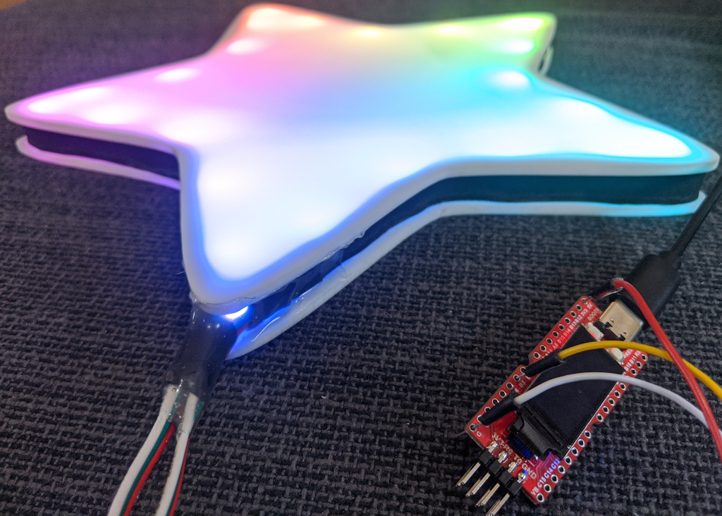
Same code, different CPU!
Remember to run make clean before you switch between platforms so that you don’t get mixed up build files. And again, you can find a full example project with this code on GitHub.
Conclusions
All in all, this worked pretty well; it was a bit of a rush job since I procrastinated before the holidays, but the stars held up well when I hung them up in a window and when I left them out in the rain for a little while. I bet they would come apart if you dropped them hard enough, though; the adhesive isn’t that strong. If you have any ideas about how to separate the faces in a way that is both durable and easy to assemble, I would love to hear about it! I’ve also tried using stacked laser-cut wood outlines, and that works well, but you end up with a lot of wasted wood shapes from the insides.
And it was cool to see how easy it was to add support for GD32VF103 chips to an STM32F103 application. They’re still sort of a curiosity, but hey – RISC-V 🙂


Davicious
April 4, 2020 at 9:31 am
Great post for learning a little about these GD32Vs, Thanks.
Anyway, don’t you think this RICV-V think is a little like a “storm in a glass of water”–?
Apart from “freeing” us from the ARM dependency -which to me, as embedded software developer, is almost irrelevant-, these MCUs are no very “revolutionary” in any sense -similar speed. memory and peripherals-, neither much better than the well known and old STM32F103. And only considering the ST’s STM32 line, there are like a zillion different models with any imaginable configuration.
If only there were a RISC-V model with several little cores in the same MCU, that really would be interesting–!
Vivonomicon
April 14, 2020 at 11:35 am
Maybe, but it’s still a young instruction set. ARM Cortex-M chips benefit from decades of improvements and toolchain optimizations, and it’ll probably be a few years before there are many options for RISC-V chips. Even so, the GD32VF103 seems like an incremental improvement over the STM32F103 in terms of speed and RAM.
The RISC-V ISA does support multiple harts and multiple cores, so you could write a small microcontroller CPU with several cores if you wanted to.
Personally, I find it exciting because it allows anyone in the world to write a general-purpose CPU into their hardware designs without also needing to write a compiler. It might also bring costs down a bit, and encourage companies like ARM to have less hostile behavior towards smaller entities by introducing a competitive alternative.
Davicious
April 28, 2020 at 11:38 am
Yeah. Thinking of it, from a tinkering perspective, a good use would be put some variant of an RISC-V core inside a FPGA.
That’s something you can’t do with a ARM core.
Regards.
Regards.