
I haven’t written about STM32 chips in a little while, but I have been learning how to make fun displays and signage using colorful LEDs, specifically the WS2812B and SK6812 ‘Neopixels’. I talked about the single-wire communication standard that these LEDs use in a post about running them from an FPGA, and I mentioned there that it is a bit more difficult for microcontrollers to run the communication standard. If you don’t believe me, take a look at what the poor folks at Adafruit needed to do to get it working on a 16MHz AVR core. Yikes!
When you send colors, the 1 bits are fairly easy to encode but the 0 bits require that you reliably hold a pin high for just 250-400 nanoseconds. Too short and the LED will think that your 0 bit was a blip of noise, too long and it will think that your 0 is a 1. Using timer peripherals is a reasonable solution, but it requires a faster clock than 16MHz and we won’t be able to use interrupts because it takes about 20-30 clock cycles for the STM32 to jump to an interrupt handler. At 72MHz it takes my code about 300-400 nanoseconds to get to an interrupt handler, and that’s just not fast enough.
There are ways to make it faster, but this is also a good example of how difficult it can be to calculate how long your C code will take to execute ahead of time. Between compiler optimizations and hardware realities like Flash wait-states and pushing/popping functions, the easiest way to tell how long your code takes to run is often to simply run it and check.
Pulseview diagram of ‘101’ in Neopixel. I can’t be sure, but I think the ‘0’ pulse might be about 375 nanoseconds long.
Which brings us to the topic of this tutorial – we are going to write a simple program which uses an STM32 timer peripheral to draw colors to ‘Neopixel’ LEDs. Along the way, we will debug the program’s timing using Sigrok and Pulseview with an affordable 8-channel digital logic analyzer. These are available for $10-20 from most online retailers; try Sparkfun, or Amazon/eBay/Aliexpress/etc. I don’t know why Adafruit doesn’t sell these; maybe they don’t want to carry cheap generics in the same category as Salae analyzers. Anyways, go ahead and install Pulseview, brush up a bit on STM32 timers if you need to, and let’s get started!
A Quick Neopixel Test Program
So let’s start by writing a quick program to send a stream of 10101010 bytes with the Neopixel interface timing. We don’t know how long each pulse will turn out to be yet, but the basic logic will look the same as the state machine from the FPGA example. We send 24 bits of color for each LED, and we can send each bit of color with a simple process:
- Set a timer to wait for X ticks. (X will be lower for a
0, higher for a1.) - Pull the GPIO pin high.
- Start the timer.
- Wait for the timer’s counter to be >= X.
- Pull the GPIO pin low.
- Move on to the next bit.
This process is difficult to get working with a slow-ish chip like a 16MHz AVR or MSP430 core because steps 3-4 often take too long, but ARM Cortex-M cores like the STM32 can usually run fast enough to manage it. Note that you will need to temporarily disable hardware interrupts if your program uses them, because any unexpected delays between the pin toggles can throw things off.
The example code that I put on Github tries to support some F0, F1, and L4 chips, but to save space I’ll just present code written for an STM32L432KC ‘Nucleo’ board. ST sells them for about $11. I was thinking of using one of the timer’s PWM ‘one-shot’ modes with a different duty cycle for 0s and 1s, but I wanted something that would work on any GPIO pin, not just ones that are mapped to timer peripherals. So:
#include <stdint.h>
#include "stm32l4xx.h"

/**
 * Main program.
 */
#define PB_LED (0)
int main(void) {
  // Set 3 wait-states in flash, enable prefetching.
  FLASH->ACR    |=  (FLASH_ACR_LATENCY_3WS |
                     FLASH_ACR_PRFTEN      |
                     FLASH_ACR_ICEN        |
                     FLASH_ACR_DCEN);
  RCC->CR       |=  (RCC_CR_HSION);
  while (!(RCC->CR & RCC_CR_HSIRDY)) {};
  // Set the PLL to HSI/2 * 18 = 72MHz.
  RCC->PLLCFGR  &= ~(RCC_PLLCFGR_PLLM |
                     RCC_PLLCFGR_PLLN |
                     RCC_PLLCFGR_PLLR |
                     RCC_PLLCFGR_PLLSRC);
  // The STM32L4 has multiple PLLs; 'PLLR' is the main output.
  RCC->PLLCFGR  |=  (RCC_PLLCFGR_PLLM_0 |
                    (18 << RCC_PLLCFGR_PLLN_Pos) |
                     RCC_PLLCFGR_PLLREN |
                     RCC_PLLCFGR_PLLSRC_HSI);
  // Enable the PLL and set it as the system clock.
  RCC->CR       |=  (RCC_CR_PLLON);
  while (!(RCC->CR & RCC_CR_PLLRDY)) {};
  RCC->CFGR     &= ~(RCC_CFGR_SW);
  RCC->CFGR     |=  (RCC_CFGR_SW_PLL);
  while (!(RCC->CFGR & RCC_CFGR_SWS_PLL)) {};

  // Enable the GPIOB and TIM16 peripherals.
  RCC->AHB2ENR |= RCC_AHB2ENR_GPIOBEN;
  RCC->APB2ENR |= RCC_APB2ENR_TIM16EN;

  // Output type: Push-pull, high-speed.
  GPIOB->MODER    &= ~(0x3 << (PB_LED * 2));
  GPIOB->MODER    |=  (0x1 << (PB_LED * 2));
  GPIOB->OTYPER   &= ~(0x1 << PB_LED);
  GPIOB->OSPEEDR  |=  (0x3 << (PB_LED * 2));
  GPIOB->ODR      &= ~(1 << PB_LED);

  // Setup neopixel timer. First, make sure it is off..
  TIM16->CR1 &= ~(TIM_CR1_CEN);
  // Set prescaler, auto-reload registers.
  TIM16->PSC  =  (0);
  TIM16->ARR  =  (0xFFFF);
  // Apply settings w/ timer update event.
  TIM16->EGR |=  (TIM_EGR_UG);
  // Test color.
  uint32_t color = 0x00AAAAAA;
  while (1) {
    // Send a test color; 0xAAAAAA is '1010...'
    int i, pulse_w;
    for (i = 0; i < 24; ++i) {
      if (color & (1 << (23 - i))) {
        pulse_w = 90;
      }
      else {
        pulse_w = 30;
      }
      TIM16->CR1  |=  (TIM_CR1_CEN);
      GPIOB->BSRR |=  (1 << PB_LED);
      while (TIM16->CNT < pulse_w) {};
      GPIOB->BSRR |=  (1 << (16 + PB_LED));
      TIM16->CR1  &= ~(TIM_CR1_CEN);
      TIM16->CNT   =  (0);
    }
  }
}
I guess you could also use a loop of asm("nop"); instructions if you’re going to guess-and-check, but however you decide to do things it starts with a guess of how many time units a 0 and a 1 will take. And you only really need to worry about the ‘high’ signal length, because the ‘low’ signal can be stretched out as long as you send another bit before the ‘latch’ time, which I think is around 10-50 microseconds for WS2812Bs and 50-100 microseconds for SK6812s.
Pulseview
Now we need to figure out how long each pulse actually lasts, and adjust them to fit the 350 and 900 nanosecond high-times that are expected for a 0 and 1 bit respectively. An oscilloscope is a good way to do this if you have one and know how to use it, but the sort of digital logic analyzer that I mentioned earlier is good enough for this purpose. You can get started pretty easily by installing Pulseview, which is a graphical interface built around the Sigrok project. Sparkfun has a good tutorial with instructions for installing and setting up these programs.
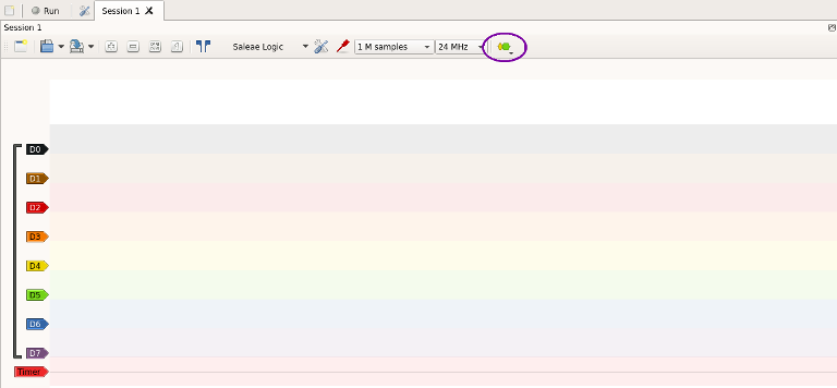
Once you have your logic analyzer plugged in and open in Pulseview, you can connect its ground cable to your microcontroller’s ground, and plug the signal wire into one of the channel cables; I usually pick channel 0 or 1, but it doesn’t matter. Make sure that the program is set to collect samples at 24MHz (the fastest supported by these devices), and click the ‘Run’ button with a grey circle next to it. The program should collect however many samples you asked for (the default is 1 million) and draw them in the main display:
‘1’ and ‘0’ Timing signals.
If you zoom in you can see that 1 pulses take longer than 0 pulses, and you can see a general timescale along the top of the screen, but it’s not immediately clear how long each pulse lasted. Pulseview supports a variety of secondary views which can automatically translate signals into other formats, so let’s add one to this view. Click the ‘Protocol Decoder’ menu (circled in purple), and click on the option that says ‘Timing’. A new bar should be added to the bottom of the display:
Pulseview View
You can move this signal up and down in the view by clicking and dragging its label along the left sidebar – I moved mine to the top so that it was close to the ‘channel 0’ signal. And you can configure it by double-clicking on the label. I set the ‘averaging period’ to zero so that it only showed the duration of each pulse.
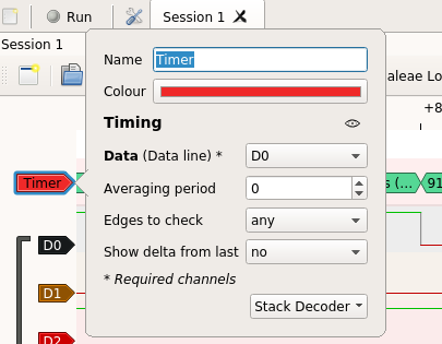
Timer configuration menu
And now it’s easy to see how long each pulse lasted. The 0 pulse took too long, and so did the 1 pulse. I’m actually not sure if a 1 pulse has a maximum high-time – the LED chip might just wait for a falling edge – but I’d like to keep each bit close to 1.25 microseconds because less idle CPU time is usually better:

Pulseview timing view of some too-long pulses.
Changing the the values from 90 and 30 to 50 and 10 seems to get better results of 375 / 958 nanoseconds – then we just need to send 24 color bits and a latching signal instead of an endless stream of 10101010. The 32-bit coding for a color is 00GGRRBB (Green/Red/Blue), so this code should send one pixel of purple:
// (...setup...)
// Test color.
uint32_t color = 0x0000AAAA;
#define PB_LED (0)
while (1) {
  // Send a test color; 0xAAAAAA is '1010...'
  int i, pulse_w;
  for (i = 0; i < 24; ++i) {
    if (color & (1 << (23 - i))) {
      pulse_w = 50;
    }
    else {
      pulse_w = 10;
    }
    TIM16->CR1  |=  (TIM_CR1_CEN);
    GPIOB->BSRR |=  (1 << PB_LED);
    while (TIM16->CNT < pulse_w) {};
    GPIOB->BSRR |=  (1 << (16 + PB_LED));
    TIM16->CR1  &= ~(TIM_CR1_CEN);
    TIM16->CNT   =  (0);
  }
  for (i = 0; i < 200000; ++i) {
    asm("NOP");
  }
}
After building and uploading that, the first LED in a strand turns purple. Hooray:
One Purple Neopixel. New band name?
Desperate Times
This isn’t a great way to do things, but it worked fine for the nicer Cortex-M3 and -M4 chips which could run at 72MHz – the STM32L432KC can actually do 80MHz, but I ran it at the same 72MHz speed as the cheap and popular STM32F103C8 to demonstrate how the timings worked out differently even with the same core clock speed. The L432 is newer, and it includes more options for caching and speeding up flash access. It also uses a Cortex-M4 core with a larger instruction set, so even though both chips run at 72MHz, the STM32L432 performs better in the actual application here; the STM32F103 barely even has time to run one cycle of its ‘while’ loop.
With so much variance between similar chips made by the same manufacturer, you can see why I sometimes reach for the oscilloscope instead of the calculator for things like this. A few hundred nanoseconds don’t usually matter, but here it’s the difference between the right color and a blinding white light. And along those lines, when I tried to get this working on the very affordable STM32F030K6, I found that its maximum 48MHz clock speed was a bit too slow to reliably send a 0 – it ended up taking about 500 nanoseconds to toggle the pin with the register write and while loop in between.
There are a few ways that this code could be faster. I could put the code in RAM and run it from there, or maybe write a section of assembly code to quickly check the counter register. But I didn’t want to change the code too much, so it seemed easiest to just try running the chip a little faster. ST says not to do this all over the reference manual, so this may or may not damage the chip – try it at your own risk.
But if you look at the FLASH_ACR register description in the reference manual, (section 3.5.1) it says that there are 3 bits available for setting the number of wait states. It only lists 000 (0-24MHz) and 001 (24-48MHz) as available options, but I tried using 010 (2 wait-states for 48-72MHz?) with a PLL multiplication of 16 for its HSI/2 input for a 64MHz core clock speed, and that seemed to work. I wonder how fast you could go? It sounds like it depends on what peripherals you want to use, but it looks like these STM32 chips might be significantly faster than they appear for general-purpose applications.
Conclusions
This isn’t exactly an elegant way to figure out how long your code will take to run , and I don’t usually like solutions that rely on “magic numbers”. But it is easy and fast, so when you find yourself on a tight timeline that just needs some goddamned pretty sparkly colors yesterday, these logic analyzers are nice tools to have.
Here’s a Github repository with example code using the same arm-none-eabi-gcc / make toolchain as the last few of these write-ups. It’s not exactly a library, but it works with a few chips and it should demonstrate the basic idea.

