
Making a Retro Wall Clock
It’s good to know what time it is, and once you work out how to use a RealTime Clock module, making a clock display seems like a natural next step. 7-segment LED displays used to be the go-to way to display time digitally before LCD and OLED screens got so cheap, and I thought it would be fun to make a more modern take on them with diffused multicolor LEDs for the actual lighting. I would like to write a post about drawing to traditional 7-segment digits using shift registers, but this project uses the easy-to-wire ‘Neopixels’ that we all know and love.
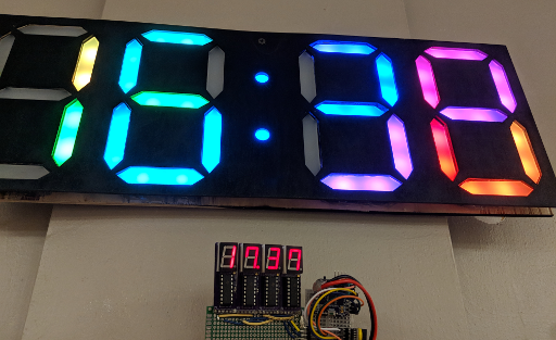
The one on the bottom doesn’t know about daylight savings, but you get the idea.
You’ll need a few materials for this project if you want to follow along:
- Access to a laser cutter and a 3D printer.
- About 6 x 12″ of 1/8″-thick ‘frosted’ acrylic, to diffuse the LEDs. (About 150 x 300mm, 3mm thick)
- Enough plywood to make a clock face for the front and back; I wound up using about 500 x 200mm each.
- 58 individually-addressable RGB LEDs. (28 sets of 2 for each segment of the 4 digits, and 2 more for the colon dots.)
- A DS3231 or similar realtime clock module.
- A microcontroller to run everything; I used an ATMega328 on an “Arduino” nano board to keep the code simple.
- Craft supplies: solder, soldering iron, glue, hot glue gun, wire, etc.
For the LEDs, I cut lengths off of a reel of LED strip that I ordered off Amazon; I think it used SK6812 LEDs and had 30 LEDs / meter. For the two dots of the colon, you can also buy small single-LED boards that are about 10mm in diameter and usually have WS2812B LEDs. I didn’t run into any problems stringing SK6812 and WS2812B LEDs together with Adafruit’s “Neopixel” library, but caveat emptor.
Replacing Broken Car Speakers
Some Cars are Old
Recently, I bought a very used car in the hopes of modifying it to use a parallel-hybrid drivetrain. I’d like to cut the driveshaft and slot an electric motor inline with it, and that will probably be the subject of future posts if I can find a garage willing to do most of the heavy lifting and cutting.
But in the meantime, what sort of car do you get if you’re thinking of cutting its driveshaft in half? A cheap one, of course – and my choices were further limited by a few basic requirements:
- The car should actually be a small pickup truck; the bed is an ideal place to put the heavy batteries, they tend to have a lot of ground clearance for fitting a bulky motor underneath the chassis which means little or no changes to the bodywork, and passenger space is not a consideration in this build.
- It should be rear-wheel drive. Since I am planning to add a motor between the transmission and the differential, there needs to be enough space along the driveshaft to fit the motor. That means either rear-wheel drive with the engine in the front, or front-wheel drive with the engine in the back. And I don’t know of any rear-engine pickup trucks.
- It should have an automatic transmission. This kind of simple conversion leaves you with two acceleration pedals, and I don’t have enough feet to use four pedals at once.
So I wound up with a cheap-and-cheerful 1994 Toyota Pickup Truck. It doesn’t actually have a model name; in North America, the Hilux brand was renamed to “Truck” in the 1970s before eventually being replaced with the Tacoma. So this is not a luxury vehicle. It has roll-up windows, it does not have ABS, it came with a broken speedometer, and more importantly its speakers had disintegrated in the decades since 1994.
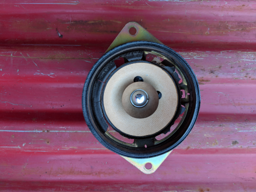
Yikes.
That’s no good, and it sounded like the buzzing of a thousand wasps. Plus, replacing your speakers seems like a pretty easy first project if you want to learn about a car. You only have to remove a few interior panels, and your sound system is a safe thing to break compared to say, your brakes. So let’s get started! These specific instructions may be for a 1994 Toyota pickup, but I’ll bet the process looks similar for the front speakers of other cars.
Recycling HDPE: What Doesn’t Work
Over the past month or two, I’ve been learning about plastic recycling with a friend at a local makerspace. We decided to start out with HDPE as a nice beginner’s material, because it melts at less than 200C and tends to be fairly nontoxic. We’ve tried a few different techniques now, and we’ve learned a lot about what doesn’t work.
This is an exciting field and we hope to make a decent press for forming 3mm and 6mm-thick HDPE sheets soon, but our early designs have shown us some key difficulties to be aware of if you are planning to start recycling plastics on your own. And I’ll mention this later, but please research what you plan to recycle ahead of time and avoid plastics which might release hazardous fumes. As you will see, I am not an expert.
Our first instinct was to imitate an injection-molding press, and we started by scavenging some large heating elements from a Goodwill-sourced griddle. It consisted of four ~13-Ohm coils arranged as two parallel banks, each consisting of two elements in series. That meant an effective resistance of 13 Ohms, or a bit over 9 amps at the mains 120V which it was more or less directly connected to.
We wound up clipping the heating coils out and scavenging some of the crimped and heat-insulated wiring, strapping them to a smooth-bore metal pipe, and then soldering or spot-welding the four coils back together in their original 2×2 arrangement. Temperature monitoring is all well and good, but this was a first attempt; we just wired the coils across a 2-prong plug, and flipped a surge suppressor on and off to control the heat. A handheld infrared thermometer gave us a rough indication of the tube’s temperature, and we aimed for 350-400F to melt the HDPE.
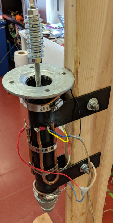
Our first attempt at a plastic-melting tube; the heating elements are the thick copper-coated wires, and the beige wires connect directly to a 2-prong wall plug.
“Bare Metal” STM32 Programming (Part 7): Embedded C++ Inheritance
As you start to re-use components like sensors and displays, you might start to get frustrated with how long it takes to set up new projects. Copying and cleaning code between old working examples and new ideas can be time-consuming and tedious. It’s much easier to simply copy a few portable library files around. While there are plenty of existing libraries for these sorts of peripherals and external devices, it’s good to learn how to write your own, and this is also a good way to demonstrate a few ‘gotchas’ that you should be aware of when using C++ in an embedded application.
In this tutorial, we will walk through setting up a couple of object-oriented classes to represent a common communication ‘I/O’ peripheral model:
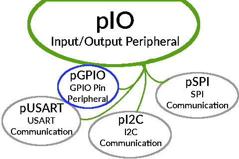
One example of what a simple common communication model could look like.
For simplicity’s sake, I’ll only cover a class for a bank of GPIO pins to demonstrate the core requirements for using C++ in an embedded application, but you can also find similar classes for the I2C peripheral and an SSD1306 OLED display in the example Github repository’s reference implementation of the concepts presented in this tutorial.
“Bare Metal” STM32 Programming (Part 6): Multitasking With FreeRTOS
In a previous tutorial, we walked through the process of setting up a hardware interrupt to run a function when a button was pressed or a dial was turned. Most chips have a broad range of hardware interrupts, including ones associated with communication and timer peripherals. There is also a basic ‘SysTick’ timer included in most ARM Cortex-M cores for providing a consistent timing without needing to count CPU cycles.
One good use of that evenly-spaced timing is to run a Real-Time Operating System (often called an ‘RTOS’) to process several tasks in parallel. As you add more parts to your projects, it will become awkward to communicate with them all using a simple ‘while’ loop. And while hardware interrupts can help, it’s usually good to do as little as possible inside of an interrupt handler function.
So let’s use FreeRTOS, an MIT-licensed RTOS, to run a couple of tasks at the same time. To demonstrate the concept, we’ll run two ‘toggle LED’ tasks with different delay timings to blink an LED in an irregular pattern.

Example LED timing with two ‘toggle’ tasks delaying for different amounts of time.
This example will also add support for some faster microcontrollers; the STM32F103C8 and STM32F303K8, which are Cortex-M3 and -M4F cores respectively. The F103C8 is available on cheap ‘blue pill‘ and ‘black pill‘ boards, and ST sells a ‘Nucleo’ board with the F303K8. Both of those chips can run at up to 72MHz, and they can also get more done per cycle since they have larger instruction sets. And as usual, there is example code demonstrating these concepts on Github.
The W1209: A (sometimes) STM8-based digital thermostat
Among the cheap gadgetry that constantly spews forth from the spawning pits of consumer electronics, sometimes you can find a gem. The W1209 is an interesting board which is designed to act as a thermostat which can also switch a relay when certain temperatures are reached. It is used in everything from rice cookers to yogurt machines to people who want their A/C to only turn on when it’s hot out. Originally they shipped with an aging but fairly capable STM8S003F3 microcontroller, and they cost less than $1.50 each.
Even so, their popularity has inspired the usual imperfect cloning process, so chances are that a board you buy from ebay, Aliexpress, Taobao, or Amazon today will need some touching up before you will be able to reprogram it. In this tutorial, we will replace the microcontroller and add a few missing capacitor/resistors. Then we’ll upload a simple test program to test that the microcontroller and board both work. So here is an example of what is probably the worst possible knock-off that you could fear to get, with missing or faulty parts highlighted:
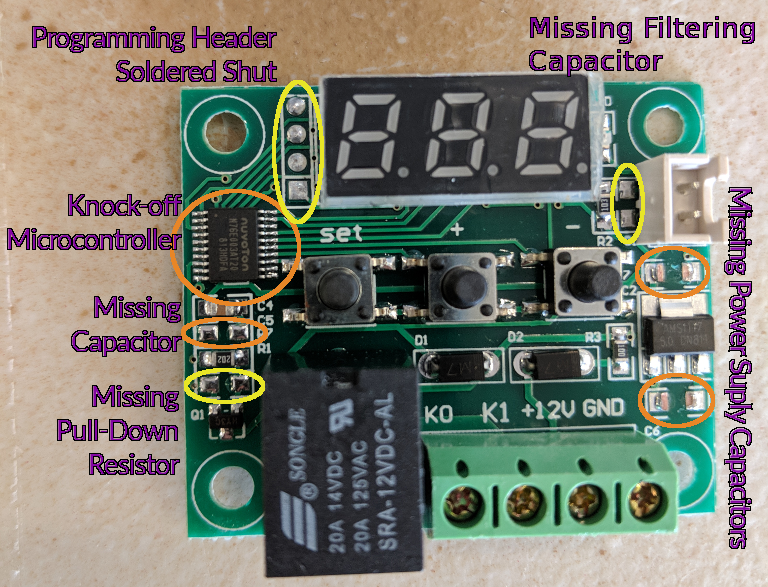
W1209 that needs fixing
Well, that’s life. You try your best, and then someone comes along and kicks you in the teeth. But let’s make some lemonade and take the opportunity to learn about fixing cheap-o knock-off circuit boards!
More Fun with Four-Wire SPI: Drawing to “E-Ink” Displays
In previous tutorials, I covered how to use the STM32 line of microcontrollers to draw to small displays using the SPI communication standard. First with software functions and small ‘SSD1331’ OLED displays, and then with the faster SPI hardware peripheral and slightly larger ‘ILI9341’ TFT LCD displays. Both of those displays are great for cheaply displaying data or multimedia content, because they can show 16 bits of color per pixel and have enough space to present a moderate amount of information. But if you want to design a very low-power application, you might want a display which does not need to constantly drain energy to maintain an image.
Enter ‘E-Ink’ displays, sometimes called “Electrophoretic Displays“. As the name implies, they use the same basic operating principle as techniques like Gel Electrophoresis, which separates polarized molecules such as DNA based on their electric charge. Each pixel in one of these displays is a tiny hollow sphere filled with oppositely-charged ink molecules, and they are separated between the top and bottom of their capsules to make the pixel light or dark. The ink remains in place even after power is removed; I think that they are suspended in a solid gel or something. Modern E-Ink modules sometimes have a third color such as red or yellow, but this post will only cover a humble monochrome display.
E-ink 😀
Drawing to a Small TFT Display: the ILI9341 and STM32
As you learn about more of your microcontroller’s peripherals and start to work with more types of sensors and actuators, you will probably want to add small displays to your projects. Previously, I wrote about creating a simple program to draw data to an SSD1331 OLED display, but while they look great, the small size and low resolution can be limiting. Fortunately, the larger (and slightly cheaper) ILI9341 TFT display module uses a nearly-identical SPI communication protocol, so this tutorial will build on that previous post by going over how to draw to a 2.2″ ILI9341 module using the STM32’s hardware SPI peripheral.
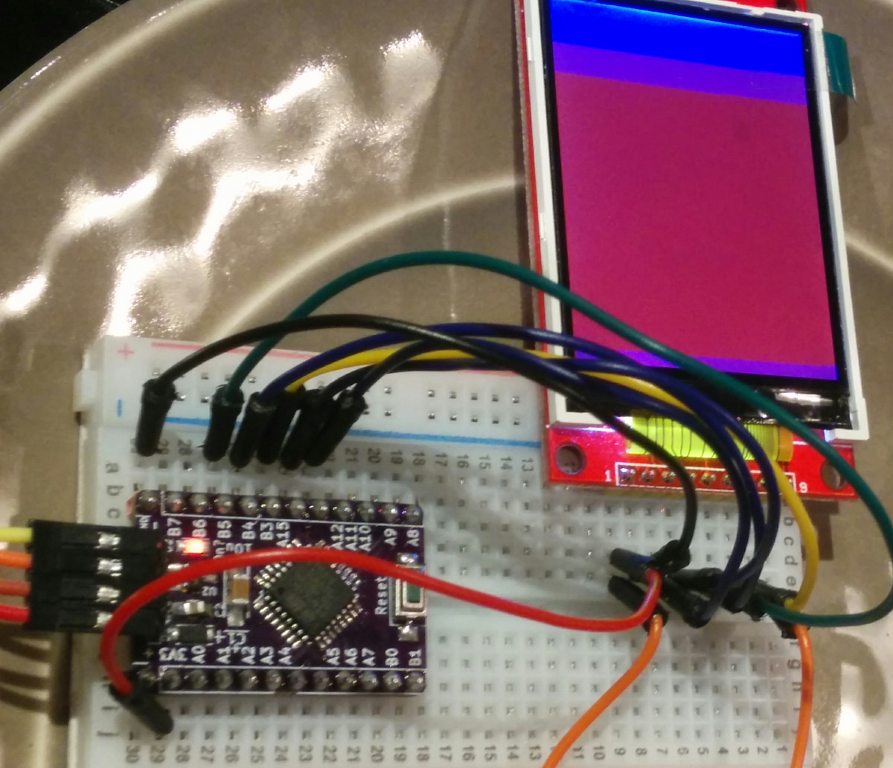
An ILI9341 display being driven by an STM32F0 chip. Technically this isn’t a ‘Nucleo’ board, but the code is the same.
We’ll cover the basic steps of setting up the required GPIO pins, initializing the SPI peripheral, starting the display, and then finally drawing pixel colors to it. This tutorial won’t read any data from the display, so we can use the hardware peripheral’s MISO pin for other purposes and leave the TFT’s MISO pin disconnected. And as with my previous STM32 posts, example code will be provided for both the STM32F031K6 and STM32L031K6 ‘Nucleo’ boards.
“Bare Metal” STM32 Programming (Part 5): Timer Peripherals and the System Clock
As you start to create microcontroller projects with more complicated logic, it probably won’t take long before you to want to add some sort of time-based functionality. How should you ask your chip to do something on a schedule?
These days, we don’t have to count clock cycles in ‘delay’ methods. The STM32 line of chips have a variety of “timer” peripherals available, and they are flexible enough to use for all kinds of different things. The “advanced control” timer peripheral is particularly complicated and I won’t try to cover it in this quick overview, but the basic and general-purpose timers are easy to get started with for simple counters and interrupts.
In this tutorial, we will write code to enable a hardware interrupt triggered by a timer peripheral, and use that to blink an LED. Just like the last couple of posts in this series, the STM32F031K6 and STM32L031K6 chips will be used to demonstrate these concepts. Since this tutorial will only use a single LED, you won’t need anything other than an affordable “Nucleo” board with one of those chips and a micro-USB cable:
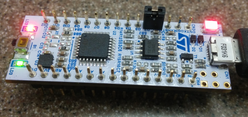
You don’t even need a breadboard!
You can double-check that the clock speeds are what we expect by counting the LED’s on/off timings against a clock. It should change about 60 times every minute with the timer set to 1 second, although the internal oscillator is not quite as precise as an external “HSE” crystal oscillator would be. As usual, an example project demonstrating this code is available in a Github repository.
Scripting a Box: Making Laser-Cut Battery Holders
Previously, I posted a tutorial about writing SVG files by hand to create simple patterns for a laser cutter to produce. But as I noted at the end of that post, writing that sort of file by hand is not a great solution. It is difficult to make a design that can be modified later, since SVG files don’t appear to have a good way to store variables yet.
So in this tutorial, I’ll go over the process of writing a simple Python script to create the same sort of “divided grid box” as in the previous SVG-writing tutorial across a wide range of dimensions. Then I’ll demonstrate how to use it to create a small 4-cell AAA battery holder out of something that isn’t plastic:
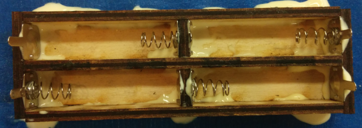
AAA battery case made of laser-cut wood
While “3D printing” a case allows you to add curves and small overhangs to hold the batteries in place, these simple laser-cut boxes can only have perpendicular edges. But I’ve found that using the sorts of spring contacts that you find in most commercial battery cases provides enough pressure to hold the batteries in place, at least until you hold the case upside down and knock it against something to pop them out.
Plus, 3D printing is comparatively slow; a battery case of this size would take between 30-60 minutes to print out on a Prusa i3 running at high speed, but a CO2 laser can cut out these parts in about 60 seconds. You do need to glue the pieces together, but if you adjusted the scripts to account for the “kerf” of your particular laser/material, you might be able to make them press-fit. Anyways, let’s get started!
Your Own Hardware: Using KiCAD to Design a Minimal STM32 Development Board
It’s great to be able to write programs for a chip’s evaluation boards, but the real strength of microcontrollers is their ability to act as a low-cost, low-power “brain” for larger designs or products. And along those lines, I’ve been writing a few tutorials about bootstrapping some basic ‘bare metal’ STM32 projects using an STM32F031K6 “Nucleo” board sold by ST.
That’s a great way to get started and test ideas out, but what if you want to try your hand at building a robot, or a home automation widget, or some other sort of complex machine? It’s nice to avoid huge messes of breadboards and wires once you have a basic prototype working, and these days it only costs a few dollars to get a small custom circuit board manufactured. The catch is, they usually take a few weeks to arrive and you need to provide the design. Still, the boards that we design in this tutorial will cost less than $2 each.
In this tutorial, we will use a suite of free software called KiCAD to produce a small example board using the same basic STM32F031K6 chip that I’ve been writing programming examples for. Our board won’t be quite as nice as ST’s, and it will require an external USB device for programming and debugging. But on the other hand, our board will be smaller and cheaper, and you will be able to put the same design onto more holistic boards with other parts for your kickass robot or electronic vehicle or <insert dream here>:
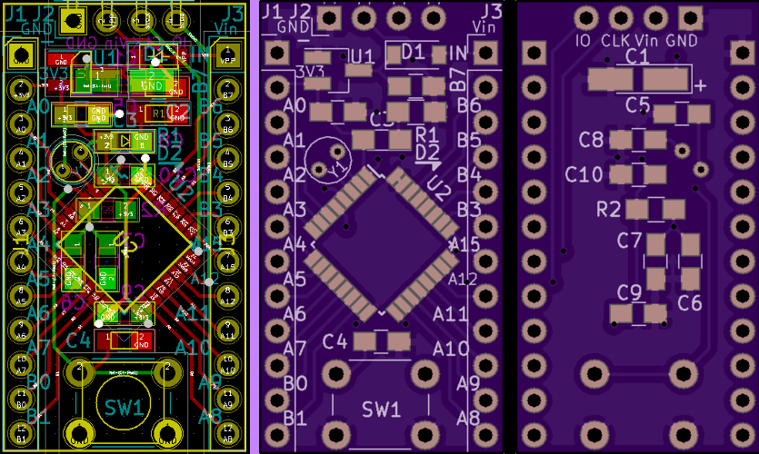
Left: A board like the one you’ll design in KiCAD. Right: OSHPark’s renders of the front and rear of the board.
The design files described in this post are all available in a Github repository, if you want a reference to follow along with.
When is Now? The DS3231 Real-Time Clock
Time may be an artificial construct, but try telling your boss that ‘Monday’ has no meaning. It is useful for a program to be able to schedule actions for a certain date, display the current time on a clock or calendar, or perform other tasks which use weird units of time like ‘seconds’ or ‘days’. For those types of tasks, an embedded developer might reach for an ‘RTC’ device, which stands for ‘Real-Time Clock’. They provide a way to keep accurate time, often with features like backup power supplies. Many RTCs also offer ‘wakeup’ alarms for other devices, so they are especially useful in energy-efficient designs.
The STM32 line of chips which I’ll continue to use in this tutorial have a built-in RTC peripheral, but they require an external 32.768KHz ‘LSE’ (Low-Speed External) crystal oscillator to keep accurate time. Also, managing the STM32’s backup power supply is sort of complicated.
Instead, this tutorial will walk through using the ‘I2C’ peripheral on an STM32 chip to communicate with a cheap DS3231 RTC module. Specifically, I will talk about a widely-available board labeled ZS-042, which includes 4KB of EEPROM on its I2C bus and space for a “coin cell” battery to provide several years of backup power. But the same commands should work with other DS3231 boards, such as the smaller ones in the upper-left here:
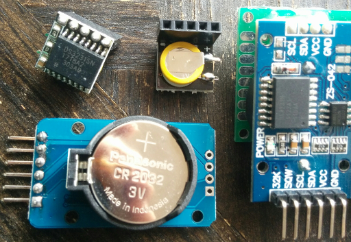
A handful of DS3231 modules and their backup batteries.
An example project demonstrating the concepts outlined in this post using either an STM32F031K6 or STM32L031K6 “Nucleo” board is available on Github.