
“Bare Metal” STM32 Programming (Part 4): Intro to Hardware Interrupts
In a previous entry in this tutorial series, I tried to walk through some basic steps for writing an example STM32 program which toggled an LED on and off when a button is pressed. But that program only checked the button’s status once every cycle of the ‘main’ loop, and in a complex application each loop iteration could take a fairly long time. If a button press were very short and our application was busy for a long time, the program could miss the input.
When you want to respond to input very quickly and consistently on a microcontroller, it is usually a good idea to use a ‘hardware interrupt’ to run some code when certain hardware events are detected. In this tutorial, we will look at the STM32’s ‘EXTI’ interrupt lines, which can be set to trigger when the state of a GPIO pin changes.
And once we have a simple ‘button press’ interrupt triggering, we can easily demonstrate a real-world use by extending it to listen for faster inputs such as “rotary encoder” dials:
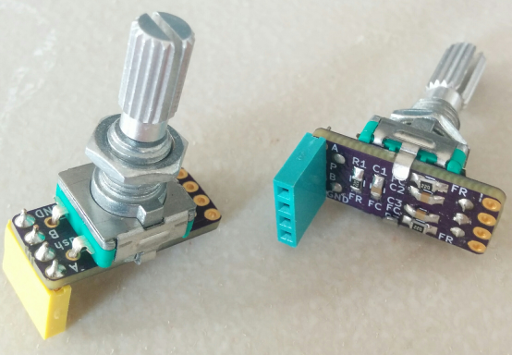
A couple of “rotary encoder” dials – the small resistors and capacitors on the back are for debouncing.
This type of dial ‘clicks’ in small steps when turned in either direction; they are nice tactile inputs, but it can be difficult to read them without hardware interrupts because of the large number of rapid pulses that they can generate when you twist them. So let’s get started!
STM32 Software SPI SSD1331 Sketch
In a previous post, I wrote about designing a ‘breakout board’ for an SSD1331 OLED display with 96×64 pixels and 16 bits of color per pixel. With the hardware already put together, this post will cover writing a basic software driver for the displays. To keep things simple, we will talk to the display using software SPI functions instead of the STM32’s SPI hardware peripheral.
If you want to skip assembling your own boards, you can also buy a pre-made display such as this one sold by Adafruit. They have also written a library for these displays which works with several common types of microcontrollers, if you just want to use them without worrying about the display settings. But if you want to try understanding this sort of communication at a lower level, read on!
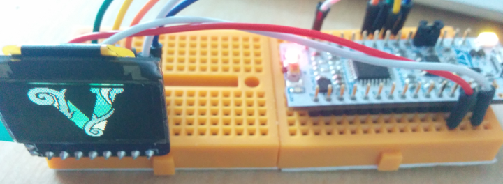
The finished program will display a predefined framebuffer, like this little logo!
Since many small microcontrollers – including the STM32F031K6 discussed in this example – don’t have 12KB of RAM available to store a 96×64 display at 16 bits per pixel, I’ll use a framebuffer with just 4 bits per pixel in this example (3KB), and map those 16 values to a palette. This example builds on the first few “Bare Metal STM32 Programming” tutorials that I’ve been writing, so here is a Github repository with the entire example project (including supporting files) if you don’t want to read those.
“Bare Metal” STM32 Programming (Part 3): LEDs and Buttons!
In a previous post, I walked through creating a basic project for an ‘STM32F031K6’ microcontroller to boot the chip into a ‘main’ C method. But the actual program didn’t do much, so in this post we will learn how to use the STM32’s ‘GPIO’ peripheral to listen for a button press and blink an LED.
The ‘Nucleo’ boards provided by ST have an LED already built into the board, but they don’t have a button (besides the reset one,) so we’ll need to connect one externally:
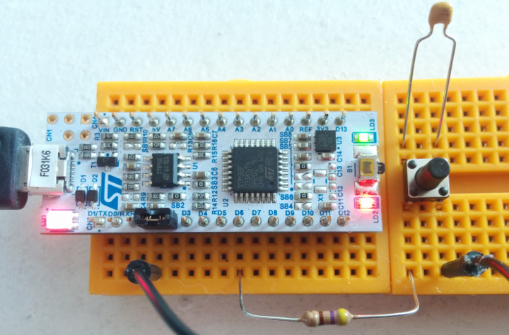
‘Nucleo’ STM32F031K6 board with a button.
The green ‘LD3’ LED is attached to pin B3 on the board. The 100nF capacitor across the button should help reduce noise, one side of the button connects to ground through a jumper wire, and I put a 470Ω resistor between the other side of the button and pin B1.
Strangely, the B1 pin is labeled ‘D6’ on the Nucleo boards; I think that ST wanted to use the same footprint and labeling as the popular Arduino Nano. You can find the actual pin mappings in section 6.11 of this reference document, or they’re also printed on the informational card that comes with the board. The resistor and capacitor are both optional – they’re just a very simple form of debouncing. Next up, the code!
DIY OLED Display Boards: SSD1306 and SSD1331
OLED displays are excellent solutions for low-power, high-visibility UIs that don’t need to depict much detail and can be smaller than a square-inch or two. These days, they are cheap and available enough to be viable options for the hobbyist:
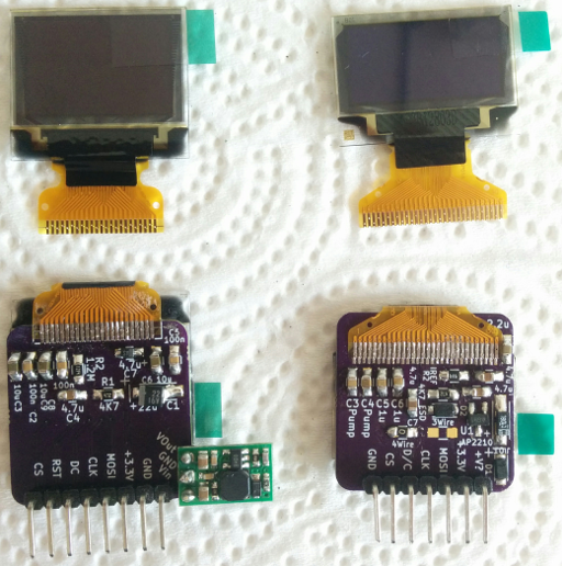
Top: The display panels as they arrive in the mail. Bottom: Boards with the circuits described in this post – the panels are glued to the other side.
These are two small display panels which you can find on Taobao, Alibaba, or eBay in small quantities for roughly $2-4 each. The one on the left is a 96×64-pixel SSD1331 16-bit color display. The one on the right is a 128×64-pixel SSD1306 monochrome display where each pixel is either ‘off’ or ‘on’ – typically ‘on’ is a white or blue color. Some of them have a row of 16px along the top set to yellow, but each pixel is still only one color.
In this post, we will walk through the circuitry (although not the code) required to control these displays using a microcontroller, including circuit schematics for laying out a ‘breakout board’ in your preferred EDA program – I used KiCAD, and I’ll also provide a link to those projects if you don’t want to design a new board.
Writing a Box: SVG Basics
Lately, I’ve been looking for ways to get people interested in basic electronics, and things like kits and/or lessons seem like a great way to do that. I’ve also been looking for ways to learn about making things with a laser cutter, so I decided to put together a stack-able box that could double as storage and a display for available electronics parts at a local makerspace.
The basic idea was simple; start with a box ‘outline’ similar to those generated by Makercase, and then lay out a grid pattern of ‘dotted lines’ to slot crenellated dividers into. I wanted something like a shallow tray, with several horizontal and vertical dividers to hold different types of parts. What could possibly go wrong?
At this point, with a basic idea and maybe a quick sketch, most sane people would open up a program like Autodesk Inventor, Solidworks, or Adobe Illustrator. Options like Inkscape, OpenSCAD, or SolveSpace would also work well if you like free software. But after having some trouble with SVG exports, I wondered if it might make sense to just write the files by hand, for a simple grid pattern.
I guess it depends on your definition of ‘sense’! In this post, we’ll learn how to write SVG files for a small laser-cut ‘test’ box:
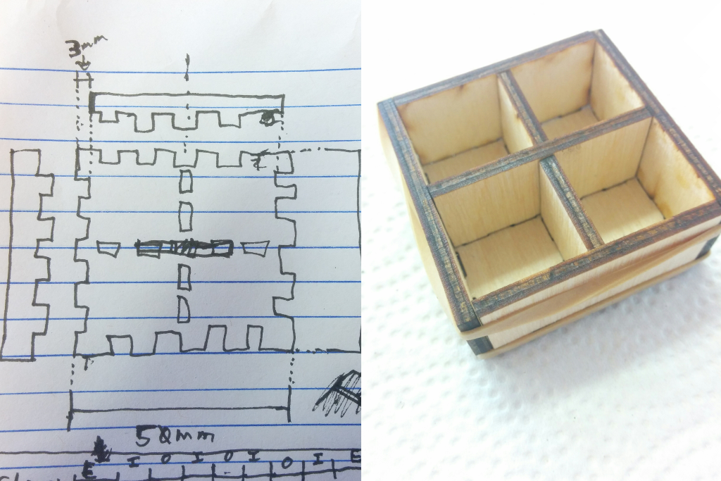
Quick sketch of a test box, and what it’ll look like.