
Among the cheap gadgetry that constantly spews forth from the spawning pits of consumer electronics, sometimes you can find a gem. The W1209 is an interesting board which is designed to act as a thermostat which can also switch a relay when certain temperatures are reached. It is used in everything from rice cookers to yogurt machines to people who want their A/C to only turn on when it’s hot out. Originally they shipped with an aging but fairly capable STM8S003F3 microcontroller, and they cost less than $1.50 each.
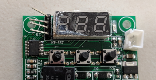
Even so, their popularity has inspired the usual imperfect cloning process, so chances are that a board you buy from ebay, Aliexpress, Taobao, or Amazon today will need some touching up before you will be able to reprogram it. In this tutorial, we will replace the microcontroller and add a few missing capacitor/resistors. Then we’ll upload a simple test program to test that the microcontroller and board both work. So here is an example of what is probably the worst possible knock-off that you could fear to get, with missing or faulty parts highlighted:
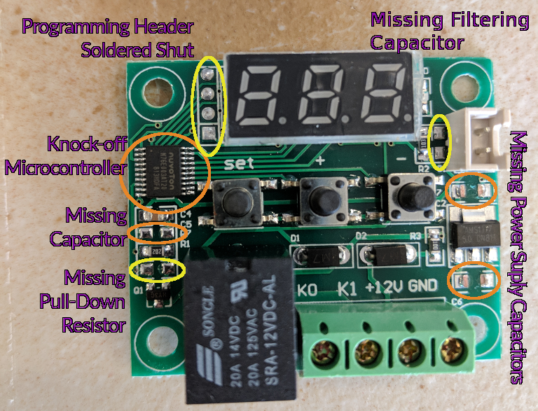
W1209 that needs fixing
Well, that’s life. You try your best, and then someone comes along and kicks you in the teeth. But let’s make some lemonade and take the opportunity to learn about fixing cheap-o knock-off circuit boards!
A note before we start: unfortunately, as of the time of writing, the dirt-cheap STM8S003F3 microcontrollers are out of stock just about everywhere. Mouser reports factory lead times of 34 flippin’ weeks, so perhaps it is not surprising that cheap generic boards containing genuine parts are getting to be uncommon. It looks like you might still be able to find STM8S103F3 chips if you’re quick – check Octopart. They are pin-compatible, but a bit more expensive because they have some extra features. Another option is to buy some cheap STM8S103F3 development ‘blue boards’ and steal their MCU cores; there’s probably large stocks of them backed up, and they cost about $0.75-$1.50 last time I ordered a couple dozen, depending on where you order from. Check eBay, Taobao, AliExpress, etc:
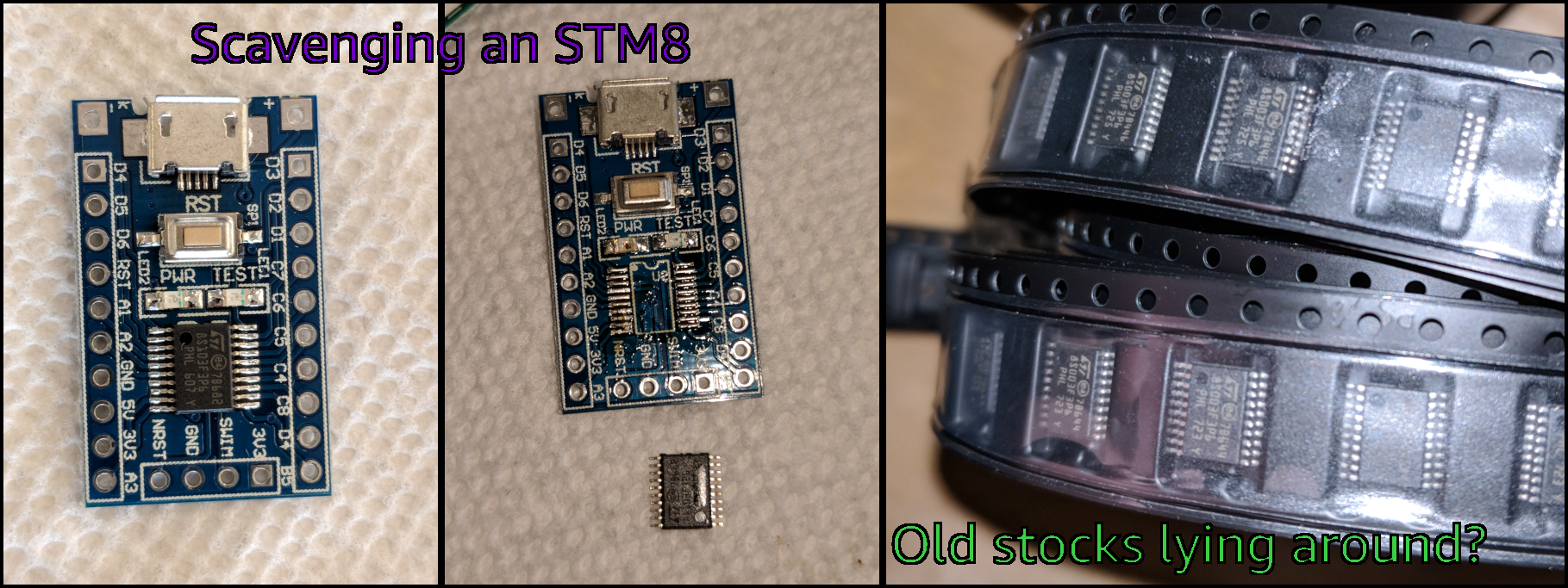
The cheap little blue boards should be easy to find if you search for something like, ‘STM8S103 development board’. Or, while the STM8 line is somewhat hard to justify using in this day and age, you might still know someone who ordered a bunch of them during a time when they weren’t so hard to find for maybe $0.25 a pop – crazy like a fox!
Step 1: Replacing Incorrect and Missing Parts
So, first take a look at your W1209 board. If it already has an STM8 microcontroller on the board and all of the empty pads circled in the picture above have parts on them, congratulations! You can skip most or all of these steps and start programming the board! Spare a thought for the rest of us.
Step 1a: Replace the Microcontroller.
The rest of us will start by replacing the microcontroller and making sure that the C5 spot is populated with a 1-microFarad ceramic capacitor. You can see that in my board, the cheap-o “nuvotron” chip doesn’t need an external capacitor and leaves the pad unpopulated. This is not what the pictures in the listing I ordered from showed, so be sure to check your listing’s reviews for actual pictures of the products that people received. Lesson learned:
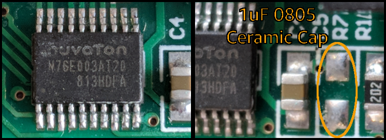
In addition to the ‘nuvotron’ chip, we need to add a 1uF capacitor in the ‘C5’ space.
To remove the microcontroller, apply lots of flux to both lines of pins – I used a flux pen made by SRA for this rework, but you may have your own preferences. Once the flux is applied, just take a heat gun and apply low heat to the corner of the board until you can see the metal starting to move around near the pins. When that happens, apply heat to the entire chip and simplly pull it off the board with some tweezers. Be careful not to burn yourself with the heat gun, and be aware that the board itself will be hot to the touch for a little bit afterwards.
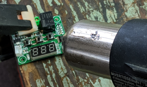
Be careful! Use a low heat setting to start, and avoid heating the LED digits or relay if possible.
A word of caution: DO NOT take your heat gun and apply a high heat setting to the entire board! You’ll notice that the microcontroller is located near a 3-digit LED display and a 12V relay, and both of those parts have plastic shells with low melting points. If you are…overenthusiastic…in your heating, you might accidentally melt them. Don’t feel bad; I did it once or twice figuring this process out, and it’s good to learn about these sorts of things on boards which cost less than a cup of coffee.
Oops. Good thing they only cost $1.
It does still seem to work, but would you trust that poor franken-board to switch a high-power load?
Step 1b: Check that it Works
Once you’ve installed the genuine STM8 chip, it’s a good idea to check that the chip works and is correctly connected to the board. The remainder of our repair work is mostly just for safety and signal stability, so we can run a quick diagnostic now to check if we can use the board at all. If it’s broken, why bother wasting time with the rest of the parts?
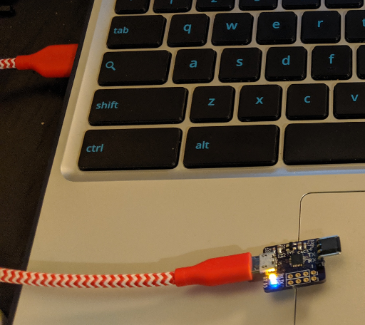
So if you’re lucky, the four programming pins will be empty through-holes at a 0.1″ pitch. But if you got unlucky like me, they might be filled in with solder. Use a solder sucker to empty them, and optionally attach a 4-pin header for programming. The connections to an ‘ST-Link’ USB module are as shown below:
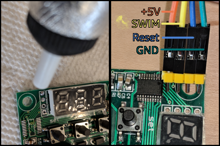
Preparing Programming Pins; Partially Painless.
Connect your programmer, and check that the chip works by flashing its factory defaults:
echo "00 00 ff 00 ff 00 ff 00 ff 00 ff" | xxd -r -p > factory_defaults.bin

stm8flash -c stlinkv2 -p stm8s003f3 -s opt -w factory_defaults.bin
Replace the -p argument with stm8s103f3 if you’re using one of those chips instead; they’re pin-compatible and should work fine. If the chip is connected correctly, you’ll see the image written successfully:
Determine OPT area
Due to its file extension (or lack thereof), "factory_defaults.bin" is considered as RAW BINARY format!
11 bytes at 0x4800... OK
Bytes written: 11
If the chip is not connected correctly, you’ll see an error; double-check the pin header connections and the solder joints on your board:
Determine OPT area
Due to its file extension (or lack thereof), "factory_defaults.bin" is considered as RAW BINARY format!
11 bytes at 0x4800... Tries exceeded
This is not a tutorial on how to program STM8 microcontrollers; here is a better one than I could write, and here is an example project which you can upload in the same way as the factory_defaults.bin file to test the board’s functions. It reads the resistive input’s analog value, prints it to the 3-digit display, and toggles the relay on / off when the ‘Set’ button is pressed. Note that the relay will not trigger if an external 12V power supply is not connected, but the LED on the board should still light up. If everything works, let’s move on to adding a few last missing components.
Step 1c: Add a Pull-Down Resistor to the Relay-Driving Transitor
Unless I’m mistaken, the missing R1 resistor is a pull-down for the gate of the NPN transistor which controls the relay. On a less poorly-cloned version that I received from another listing there was a 10K resistor here, and it does sound like a good idea to avoid leaving the gate floating in order to prevent the relay from spuriously triggering. So, let’s add an 0805-sized 10K resistor there:
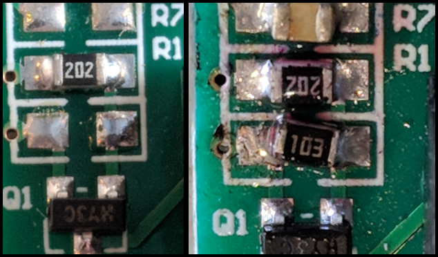
Yes, yes, it’s messy. But the ‘R1’ slot should be populated with a 10K resistor to pull the transistor’s base towards ground. You can see that it is very close to the capacitor we added in the previous step.
Step 1d: Add More Missing Capacitors
The empty C1 spot is for a filtering capacitor to reduce analog noise on the input. Typically it is filled with a 470nF capacitor but this resource suggests that that may not be the best design. It sounds like a 4.7nF – 22nF capacitor is a better choice, but it also sounds like you can leave this empty if you want, since it sounds like the capacitor would be so far away from the microcontroller that it is unlikely to be very effective at filtering. Still, I added a small ceramic capacitor.
Several of these boards also arrived with the power supply’s capacitors apparently broken off. Oh well, there are plenty of 1206 ceramic capacitors in the world. I used 10uF:
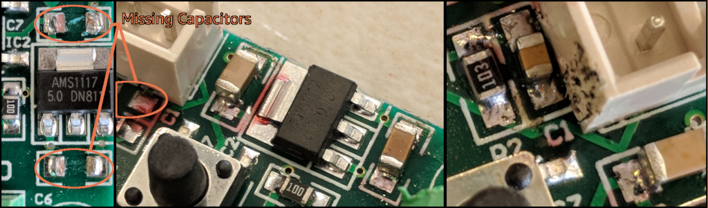
The ‘C1’ filtering capacitor is difficult to reach with an iron, but the 1206-sized 10-22uF ‘C6’ and ‘C7’ power supply ones are easy. The pictured blood of a newborn calf is optional, but adding some flux can be helpful.
Step 2: Apply 12V Power
The W1209 has four screw terminals for the higher-power connections. They are clearly marked; The K0 and K1 pins are normally disconnected, and connected by the relay when it is activated by the microcontroller. The 12V and GND terminals are self-explanatory power inputs. The 12V is regulated down to 5V for the microcontroller and LEDs, while the 12V power drives the relay.
But a word of warning, I sort of expect the relay to be of a similar quality to the other components on the board, so I wouldn’t recommend using it for anywhere near the 20A that it claims to be rated for, or allow it to operate unattended. I plan on using these for controlling recycling machines for plastics and easier metals like aluminum, where there will always be a person and an ‘off’ switch nearby when they are in use. If you depend on these relays to deliver a lot of power while nobody is around, then you’re on your own buddy.
Anyways, it’s best to use stranded wires for screw terminals, but you can use breadboard jumper wires in a pinch. Hook everything up, and the relay should click happily when it is turned on or off by the MCU. You can connect the 12V supply’s +/- wires to the +12V and GND screw terminals, and the relay’s load should connect across the K0 and K1 terminals:
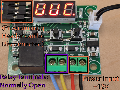
Relay and Power Connections – you can unplug the programming header if you don’t want to communicate with the microcontroller.
Conclusions
That’s all there is to it; the W1209 can be a cheap and cheerful little tool and learning platform. If you plan on using these for higher temperatures than about 100C like I do, try using a 100K thermistor instead of the 10K one which the boards usually ship with; 3D printer replacement parts work well. Another idea is to use a photodiode instead of a thermistor to perform actions based on the light level. You can use any sort of resistive input, it doesn’t have to be a thermometer.
I would like to follow up with a post that uses this board to learn about 7-segment LED displays, using relays, and listening to resistive sensors. But for now, hopefully the firmware on Github is fairly self-explanatory with the help of Lujji’s excellent introduction to the STM8.

Takhe Tado
December 25, 2018 at 6:14 am
Thanks that’s really helpful , hopefully will be filling all those missing fellow.
Mridul Kumar
August 13, 2019 at 1:04 pm
In my thermostat, Q1 transistor is missing. Is this the reason that my thermostat relay is not on?
Vivonomicon
August 22, 2019 at 10:27 am
Probably – without that NPN transistor, no current can flow through the switch that turns the relay on. I’m not quite sure which pins are the base/collector/emitter on the board, but I would guess that the pin which is connected to the ground plane is the emitter. And the pin which connects to the nearby pull-down resistor is probably the base, because pulling the base pin to ground when the microcontroller’s pin is high-impedance would help prevent the relay from turning on unexpectedly.
Good luck – I hope replacing the transistor makes your board work.
Thomas
September 16, 2019 at 9:23 pm
I’ve seen many things, but I can’t believe they’re leaving away even vital components! What’s next, the voltage regulator IC? 😀
Eswar
February 22, 2020 at 8:57 pm
Sir i brought one from amazon with c1 spot empty, will it work well like original is shall i return it
Vivonomicon
February 25, 2020 at 6:17 am
If you have the same type of board, then the small ‘C1’ capacitor near the thermistor plug should not be important.
It is supposed to hold a small filtering capacitor to increase the precision of the temperature reading, but it probably does not help much because the microcontroller is on the other side of the board.
So I can’t say for sure, but I would guess that your board would still work fine if all of the other parts are in place.
Chris
March 16, 2020 at 12:11 pm
Using a W1209 to control the cooling fan on my car and it has been working well. Today I started the car and the AMS1117 module started to smoke and burn. So the car battery is supplying 12 volt but I know alternator can take this up to 14 volt – is this likely to cause the power regulator to ‘pop’? Is this module easy to replace and is there anything else that I can add to the circuit to prevent this happening again?
Vivonomicon
March 16, 2020 at 1:31 pm
Huh, cool idea – I haven’t used these in an automotive environment, but I’ve heard that the extreme temperatures and vibrations which vehicles encounter can be very hard on parts. Electronic components which are designed for use in automobiles usually have to meet stricter requirements than regular consumer parts, with higher temperature and stress tolerances.
I wouldn’t be surprised if these super-cheap boards used super-cheap parts, so maybe the manufacturer skimped on the voltage regulator, filtering capacitors, or other components. You can see that when I ordered mine, they even came with missing parts 🙂
If you think the problem was overvoltage, maybe you could try adding one or two general-purpose diodes in series with the ‘+ voltage’ wire to drop a volt or two. But there might have been other contributing issues, like I doubt that the solder joints on these cheap boards were designed to stand up to the harsh environment of a car. You could also get short-circuits from conductive dust if the board wasn’t in an enclosure, and those could even be dangerous if you don’t have a fuse on the wires which power the board. I’m sure you know to be careful around car batteries, though; they can deliver a lot of energy very quickly.
Anyways, that sounds like a cool project – good luck, and stay safe!
EJE
April 27, 2020 at 8:21 pm
Yes, I believe you are in the right direction.
Most W1209 use a series regulator like the AMS-1117-05 to provide 5 volts to the microcontroller. But AMS-1117 maximum INPUT voltage is just 15Volts. Car alternators can provide close to 15V in a cold day (they are temperature compensated). Also induced higher voltage spikes (by electric motors, solenoids and electromagnetic clutches as in the AC compressor) superimposed to 14.4V charging levels, could “fry” that tiny AMS1117.
To see if it is worth to repair, use first a small 5.0V Supply (from a good USB charger, for instance) to see if the rest of the W1209 still works or fried altogether with the AMS1117-05.
Then it will be worth to always use any 12V linear regulator as LM7812, or LM317 (with R1=220_Ohms and R2=1800_Ohms) to get the nominal 12V to drive the any good W1209 module.
And to replace the fried AMS1117-05, use a fixed regulator as LM7805 (and low power versions), or another LM317 with R1=220Ω_again, R2=648_Ohms=1000//1800 (both in parallel=643) to achieve 5V. And for this overhauled one, you might not need the 12V regulator (although still desirable) as relay could accept noisier V > 15V spikes and SMD driving transistor circuit should have been designed to survive inductive loads from relay.
readnews
June 5, 2020 at 1:04 am
hi
first sorry for my english
i have same board
and its start reading 60 – 70 c when it should around 27 – 30 c
everything else works fine
right side of the board touched with few drops of water
can you tell me which parts i need to replace ?
thanks
Vivonomicon
June 6, 2020 at 11:11 am
It’s hard to tell, but if the readings are consistent, your thermistor might have different properties than what the code is expecting? It reads a voltage which changes as the probe’s resistance changes, instead of receiving a value in degrees C or F. Usually you need to calibrate these sorts of temperature sensors, because there is a lot of variance between different parts from different companies.
You could try recording the raw ADC values at various temperatures and plotting them on a curve, then using that as a basis for your temperature conversion.