
Circuitry
Festive Cross-Platform Holiday Lights
Across the globe, people seem to enjoy decorating their homes, communities, and outdoor spaces with lights and ornaments during the winter holidays. Maybe it helps with the depressingly early sunsets for those of us who don’t live near the equator. Anyways, I thought it’d be fun to make some ornaments with multi-color addressable LEDs last year, and I figured I’d write about what worked and what didn’t.
I didn’t have many microcontrollers at the time because I was visiting family for the holidays, so I ended up coding the lighting patterns for a cheap little STM32F103 “black pill” board which was in the bottom of my backpack. And it’s a convenient coincidence that I just started learning about the very similar GD32VF103 chips with their fancy RISC-V CPUs and nearly-identical peripheral layout, so this also seems like a good opportunity to write about how to cross-compile the same code for two different CPU architectures.

Pretty holiday stars! “Frosted white” acrylic sheets aren’t the best way to diffuse light, but they are cheap and easy to work with.
This was a fun and festive project, and it might not be a bad way to introduce people to embedded development since there are so many ways to drive these ubiquitous “NeoPixel” LEDs. Sorry that this post is a little bit late for the winter holidays – I’ve been traveling for the past few months – but maybe it’ll get you thinking about next year 🙂
I’ll talk about how I assembled the stars and what I might do differently next time, then I’ll review how to light them up with an STM32F103, and how to adapt that code for a GD32VF103. But you could also use a MicroPython or Arduino board to set the LED colors if you don’t want to muck around with peripheral registers.
Designing a Simple GPS Handheld
I’ve written a little bit in the past about how to design a basic STM32 breakout board, and how to write simple software that runs on these kinds of microcontrollers. But let’s be honest: there’s still a bit of a gap between creating a small breakout board to blink an LED, and building hardware / software for a ‘real-world’ application. Personally, I would still want a couple of more experienced engineers to double-check any designs that I wanted to be reliable enough for other people to use, but building more complex applications is a great way to help yourself learn.
So in this post, I’m going to walk through the process of designing a small ‘gameboy’-style handheld with a GPS receiver and microSD card slot, for exploring the outdoors instead of video games. Don’t get me wrong, you could still write games to run on this if you wanted to, and that would be fun, but everyone and their dog has made a Cortex-M-based handheld game console by now; there are plenty of better guides for that, and many of those authors put a lot more time into their designs and firmware than I ever did.
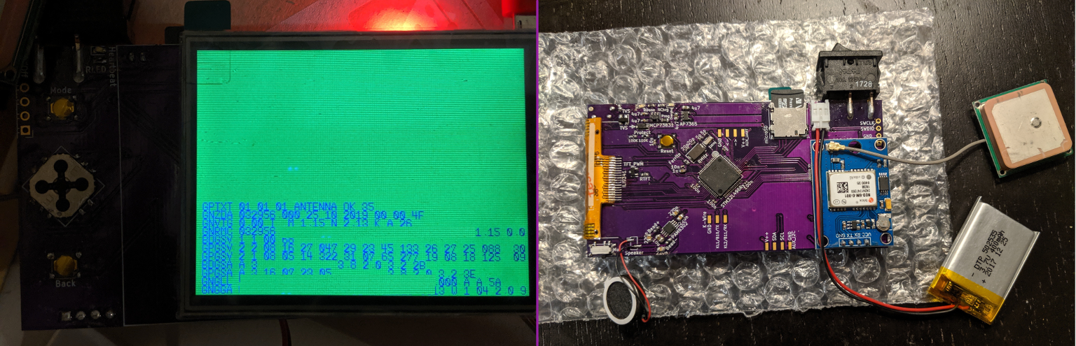
Assembled GPS Doohicky. I left too much room between the ribbon connector footprint and the edge of the board on this first revision, so the display couldn’t fold over quite right. Oh well, you live and learn.
The board design isn’t too complicated, but there are several different parts and it gets easier to make small-but-important mistakes as a design gets larger. It mostly uses peripherals that I’ve talked about previously, but there are a couple of new ones too. The display will be driven over SPI, the speaker uses a DAC, the GPS receiver talks over UART, the battery and light levels will be read using an ADC, and the buttons will be listened to using interrupts. But I haven’t written about the USB or SD card (“MMC”) peripherals, and those will need to go in a future post since I haven’t actually worked them out myself yet. Note that SD cards can technically use either SPI or SD/MMC to communicate, but the microcontroller that I picked has a dedicated SD/MMC peripheral, and I wanted to learn about it.
Anyways, if that sounds interesting, read on and let’s get started!
Simple USB / Serial Communication with the CP2102N
Several years ago, a company called Future Technology Devices International (FTDI) sold what may have been the most popular USB / Serial converter on the market at the time, called the FT232R. But this post is not about the FT232R, because that chip is now known for its sordid history. Year after year, FTDI enjoyed their successful chip’s market position – some would say that they rested too long on their laurels without innovating or reducing prices. Eventually, small microcontrollers advanced to the point where it was possible to program a cheap MCU to identify itself as an FT232R chip and do the same work, so a number of manufacturers with questionable ethics did just that. FTDI took issue with the blatant counterfeiting, but they were unable to resolve their dispute through the legal system to their satisfaction, possibly because most of the counterfeiters were overseas and difficult to definitively trace down. Eventually, they had the bright idea of publishing a driver update which caused the counterfeit chips to stop working when they were plugged into a machine with the newest drivers.
FTDI may have technically been within their rights to do that, but it turned out to be a mistake as far as the market was concerned – as a business case study, this shows why you should not target your customers in retaliation for the actions of a 3rd party. Not many of FTDI’s customers were aware that they had counterfeit chips in their supply lines – many companies don’t even do their own purchasing of individual components – so companies around the world started to get unexpected angry calls from customers whose toy/media device/etc mysteriously stopped working after being plugged into a Windows machine. You might say that this (and the ensuing returns) left a bad taste in their mouths, so while FTDI has since recanted, a large vacuum opened up in the USB / Serial converter market almost overnight.
Okay, that might be a bit of a dramatized and biased take, but I don’t like it when companies abuse their market positions. Chips like the CH340 and CH330 were already entering the low end of the market with ultra-affordable and easy-to-assemble solutions, but I haven’t seen them much outside of Chinese boards, possibly due to a lack of multilingual documentation or availability from Western distributors. So at least in the US, the most popular successor to the FT232R seems to have been Silicon Labs’ CP2102N.
It’s nice to have a cheap-and-cheerful way to put a USB plug which speaks UART onto your microcontroller boards, so in this post, I’ll review how to make a simple USB / UART converter using the CP2102N. The chip comes in 20-, 24-, and 28-pin variants – I’ll use the 24-pin one because it’s smaller than the 28-pin one and the 20-pin one looks like it has some weird corner pads that might be hard to solder. We’ll end up with a simple, small board that you can plug into a USB port to talk UART:
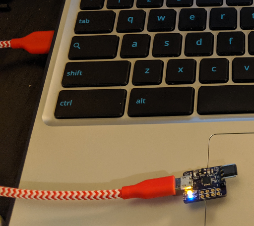
Drivers for the CP2102N are included in most popular OSes these days, including Linux distributions, so it’s mostly plug-and-play.
It’s worth noting that you can buy minimal CP2102N boards from AliExpress or TaoBao for about $1, but where’s the fun in that?
Reading Battery Voltage with the STM32’s ADC
If you choose to pursue embedded development beyond the occasional toy project, it probably won’t take long before you want to design something which runs off of battery power. Many types of devices would not be useful if they had to be plugged into a wall outlet all the time, and power efficiency is one of the biggest advantages that microcontrollers still have over application processors like the one in a Raspberry Pi.
When you do move an application to battery power, you’ll quickly discover that it is very important for your device to be able to A) charge its battery and B) alert you when its battery is running low. Not knowing whether something has hours or seconds of life left can be really annoying, and trying to use a nearly-dead battery can cause strange behavior, especially if the battery’s power drops off slowly as it dies. Most lithium-based batteries also last longer if you avoid fully discharging them – there’s some good information about lithium battery aging in this article.
So in this post, I’m going to go over a very basic circuit to power an STM32 board off of a single lithium-ion battery and monitor its state of charge. I will also talk briefly about how to add a simple battery charger to your design, but you should always independently verify any circuitry which interacts with lithium batteries! This circuit seems to work to the best of my knowledge, but don’t take my word for it; it’s very important to double- and triple-check your li-po battery circuits, because they can easily become serious fire hazards if they are handled improperly. It’s also good practice to avoid leaving lithium-ion batteries unattended while they are charging, and you should try to get batteries with built-in protection circuitry to help mitigate bad situations like over-current, under-voltage, etc.
So with those brief and not comprehensive safety warnings out of the way, let’s get started! I’ll use an STM32L4 chip for this example, but the ADC peripheral doesn’t seem to change much across STM32s. And here is a GitHub repository containing design files for a simple board which demonstrates the concepts described in this post.
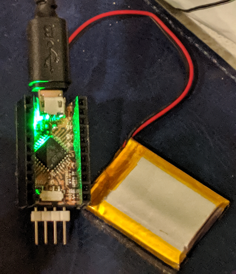
Hooray, it’s fully charged!
Keeping Up With the Moorses: Learning to Use STM32G0 Chips
Microcontrollers are just like any other kind of semiconductor product. As manufacturers learn from customer feedback and fabrication processes continue to advance, the products get better. One of the most visible metrics for gauging a chip’s general performance – and the basis of Moore’s Law – is how large each transistor is. Usually this is measured in nanometers, and as we enter 2019 the newest chips being made by companies like Samsung and Intel are optimistically billed as 7nm.
The venerable and popular STM32F1 series is more than a decade old now, and it is produced using a 130nm process. But ST’s newer lines of chips like the STM32L4 use a smaller 90nm process. Smaller transistors usually mean that chips can run at lower voltages, be more power-efficient, and run at faster clock speeds. So when ST moved to this smaller process, they introduced two types of new chips: faster ‘mainline’ chips like the F4 and F7 lines which run at about 100-250MHz, and more efficient ‘low-power’ chips like the L0 and L4 lines which have a variety of ‘sleep’ modes and can comfortably run off of 1.8V. They also have an H7 line which uses an even smaller 40nm process and can run at 400MHz.
Now as 2018 fades into history, it looks like ST has decided that it’s time for a fresh line of ‘value-line’ chips, and we can order a shiny new STM32G0 from retailers like Digikey. At the time of writing there aren’t too many options, but it looks like they’re hoping to branch out and there are even some 8-pin variants on the table. I could be misreading things, but these look like a mix between the F0 and L0 lines, with lower power consumption than F0 chips and better performance than the L0 chips. The STM32G071GB that I made a test board with has 128KB of Flash, 36KB of RAM, and a nice set of communication peripherals.
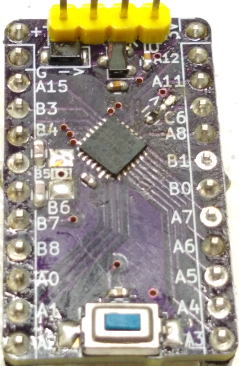
Simple STM32G0 breakout board
So what’s the catch? Well, this is still a fairly new chip, so “Just Google It” may not be an effective problem-solving tool. And it looks like ST made a few changes in this new iteration of chips to provide more GPIO pins in smaller packages, so the hardware design will look similar but slightly different from previous STM32 lines. Finally, with a new chip comes new challenges in getting an open-source programming and debugging toolchain working. So with all of that said, let’s learn how to migrate!
Basic MSP430 Hardware Design
Evaluation boards are great, but eventually you’ll want to make a design which needs to fit in a smaller space, or which uses a type of chip that doesn’t have a cheap board available. When that happens, you’ll often want to design a PCB. And it seems like most microcontrollers have similar basic hardware requirements; decoupling capacitors on the power pins, maybe a pull-up resistor and filtering capacitor on the reset pin, and a few pins which are used for debugging and programming. The MSP430 is no different, although it does have a few small quirks to be aware of.
And while I haven’t found a cheap dedicated USB device for programming MSP430 chips, you can use the debuggers built into TI’s Launchpad boards to program and debug a custom board using their “Spy-Bi-Wire” protocol. So in this tutorial, I’ll go over a basic circuit design for an MSP430FR2111 chip. It comes in a TSSOP-16 package with 3.75KB of FRAM and no Flash memory.
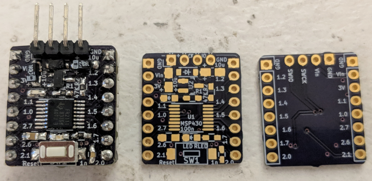
A simple example MSP430FR2111 breakout board design.
I’ll also go over the differences between programming a ‘pulsing LED’ example for the MSP430FR2111 and the MSP430G2553 that we used in the last two examples, as well as how to connect a Launchpad board’s debugger to upload programs to the custom board. So let’s get started!
Making a Retro Wall Clock
It’s good to know what time it is, and once you work out how to use a RealTime Clock module, making a clock display seems like a natural next step. 7-segment LED displays used to be the go-to way to display time digitally before LCD and OLED screens got so cheap, and I thought it would be fun to make a more modern take on them with diffused multicolor LEDs for the actual lighting. I would like to write a post about drawing to traditional 7-segment digits using shift registers, but this project uses the easy-to-wire ‘Neopixels’ that we all know and love.
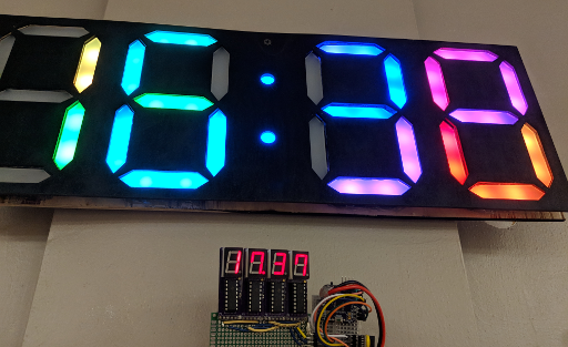
The one on the bottom doesn’t know about daylight savings, but you get the idea.
You’ll need a few materials for this project if you want to follow along:
- Access to a laser cutter and a 3D printer.
- About 6 x 12″ of 1/8″-thick ‘frosted’ acrylic, to diffuse the LEDs. (About 150 x 300mm, 3mm thick)
- Enough plywood to make a clock face for the front and back; I wound up using about 500 x 200mm each.
- 58 individually-addressable RGB LEDs. (28 sets of 2 for each segment of the 4 digits, and 2 more for the colon dots.)
- A DS3231 or similar realtime clock module.
- A microcontroller to run everything; I used an ATMega328 on an “Arduino” nano board to keep the code simple.
- Craft supplies: solder, soldering iron, glue, hot glue gun, wire, etc.
For the LEDs, I cut lengths off of a reel of LED strip that I ordered off Amazon; I think it used SK6812 LEDs and had 30 LEDs / meter. For the two dots of the colon, you can also buy small single-LED boards that are about 10mm in diameter and usually have WS2812B LEDs. I didn’t run into any problems stringing SK6812 and WS2812B LEDs together with Adafruit’s “Neopixel” library, but caveat emptor.
Recycling HDPE: What Doesn’t Work
Over the past month or two, I’ve been learning about plastic recycling with a friend at a local makerspace. We decided to start out with HDPE as a nice beginner’s material, because it melts at less than 200C and tends to be fairly nontoxic. We’ve tried a few different techniques now, and we’ve learned a lot about what doesn’t work.
This is an exciting field and we hope to make a decent press for forming 3mm and 6mm-thick HDPE sheets soon, but our early designs have shown us some key difficulties to be aware of if you are planning to start recycling plastics on your own. And I’ll mention this later, but please research what you plan to recycle ahead of time and avoid plastics which might release hazardous fumes. As you will see, I am not an expert.
Our first instinct was to imitate an injection-molding press, and we started by scavenging some large heating elements from a Goodwill-sourced griddle. It consisted of four ~13-Ohm coils arranged as two parallel banks, each consisting of two elements in series. That meant an effective resistance of 13 Ohms, or a bit over 9 amps at the mains 120V which it was more or less directly connected to.
We wound up clipping the heating coils out and scavenging some of the crimped and heat-insulated wiring, strapping them to a smooth-bore metal pipe, and then soldering or spot-welding the four coils back together in their original 2×2 arrangement. Temperature monitoring is all well and good, but this was a first attempt; we just wired the coils across a 2-prong plug, and flipped a surge suppressor on and off to control the heat. A handheld infrared thermometer gave us a rough indication of the tube’s temperature, and we aimed for 350-400F to melt the HDPE.
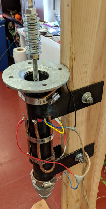
Our first attempt at a plastic-melting tube; the heating elements are the thick copper-coated wires, and the beige wires connect directly to a 2-prong wall plug.
The W1209: A (sometimes) STM8-based digital thermostat
Among the cheap gadgetry that constantly spews forth from the spawning pits of consumer electronics, sometimes you can find a gem. The W1209 is an interesting board which is designed to act as a thermostat which can also switch a relay when certain temperatures are reached. It is used in everything from rice cookers to yogurt machines to people who want their A/C to only turn on when it’s hot out. Originally they shipped with an aging but fairly capable STM8S003F3 microcontroller, and they cost less than $1.50 each.
Even so, their popularity has inspired the usual imperfect cloning process, so chances are that a board you buy from ebay, Aliexpress, Taobao, or Amazon today will need some touching up before you will be able to reprogram it. In this tutorial, we will replace the microcontroller and add a few missing capacitor/resistors. Then we’ll upload a simple test program to test that the microcontroller and board both work. So here is an example of what is probably the worst possible knock-off that you could fear to get, with missing or faulty parts highlighted:
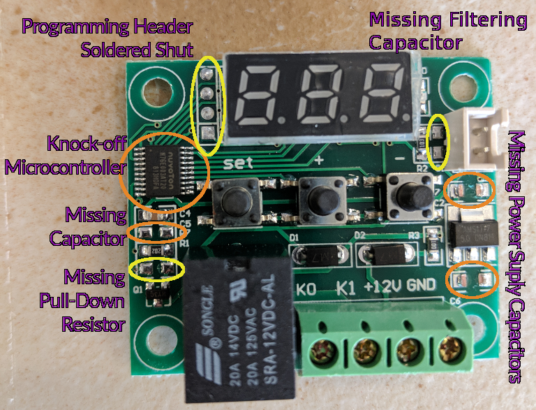
W1209 that needs fixing
Well, that’s life. You try your best, and then someone comes along and kicks you in the teeth. But let’s make some lemonade and take the opportunity to learn about fixing cheap-o knock-off circuit boards!
Your Own Hardware: Using KiCAD to Design a Minimal STM32 Development Board
It’s great to be able to write programs for a chip’s evaluation boards, but the real strength of microcontrollers is their ability to act as a low-cost, low-power “brain” for larger designs or products. And along those lines, I’ve been writing a few tutorials about bootstrapping some basic ‘bare metal’ STM32 projects using an STM32F031K6 “Nucleo” board sold by ST.
That’s a great way to get started and test ideas out, but what if you want to try your hand at building a robot, or a home automation widget, or some other sort of complex machine? It’s nice to avoid huge messes of breadboards and wires once you have a basic prototype working, and these days it only costs a few dollars to get a small custom circuit board manufactured. The catch is, they usually take a few weeks to arrive and you need to provide the design. Still, the boards that we design in this tutorial will cost less than $2 each.
In this tutorial, we will use a suite of free software called KiCAD to produce a small example board using the same basic STM32F031K6 chip that I’ve been writing programming examples for. Our board won’t be quite as nice as ST’s, and it will require an external USB device for programming and debugging. But on the other hand, our board will be smaller and cheaper, and you will be able to put the same design onto more holistic boards with other parts for your kickass robot or electronic vehicle or <insert dream here>:
Left: A board like the one you’ll design in KiCAD. Right: OSHPark’s renders of the front and rear of the board.
The design files described in this post are all available in a Github repository, if you want a reference to follow along with.
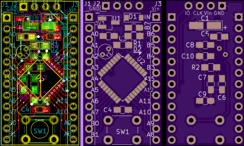
DIY OLED Display Boards: SSD1306 and SSD1331
OLED displays are excellent solutions for low-power, high-visibility UIs that don’t need to depict much detail and can be smaller than a square-inch or two. These days, they are cheap and available enough to be viable options for the hobbyist:
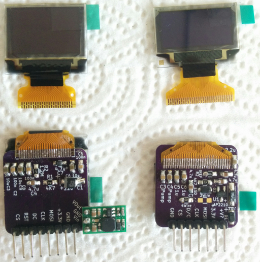
Top: The display panels as they arrive in the mail. Bottom: Boards with the circuits described in this post – the panels are glued to the other side.
These are two small display panels which you can find on Taobao, Alibaba, or eBay in small quantities for roughly $2-4 each. The one on the left is a 96×64-pixel SSD1331 16-bit color display. The one on the right is a 128×64-pixel SSD1306 monochrome display where each pixel is either ‘off’ or ‘on’ – typically ‘on’ is a white or blue color. Some of them have a row of 16px along the top set to yellow, but each pixel is still only one color.
In this post, we will walk through the circuitry (although not the code) required to control these displays using a microcontroller, including circuit schematics for laying out a ‘breakout board’ in your preferred EDA program – I used KiCAD, and I’ll also provide a link to those projects if you don’t want to design a new board.