
MSP430 Baremetal Examples
Basic MSP430 Hardware Design
Evaluation boards are great, but eventually you’ll want to make a design which needs to fit in a smaller space, or which uses a type of chip that doesn’t have a cheap board available. When that happens, you’ll often want to design a PCB. And it seems like most microcontrollers have similar basic hardware requirements; decoupling capacitors on the power pins, maybe a pull-up resistor and filtering capacitor on the reset pin, and a few pins which are used for debugging and programming. The MSP430 is no different, although it does have a few small quirks to be aware of.
And while I haven’t found a cheap dedicated USB device for programming MSP430 chips, you can use the debuggers built into TI’s Launchpad boards to program and debug a custom board using their “Spy-Bi-Wire” protocol. So in this tutorial, I’ll go over a basic circuit design for an MSP430FR2111 chip. It comes in a TSSOP-16 package with 3.75KB of FRAM and no Flash memory.
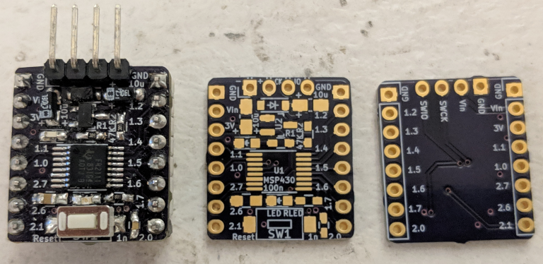
A simple example MSP430FR2111 breakout board design.
I’ll also go over the differences between programming a ‘pulsing LED’ example for the MSP430FR2111 and the MSP430G2553 that we used in the last two examples, as well as how to connect a Launchpad board’s debugger to upload programs to the custom board. So let’s get started!
Basic Low-Power Design: Sleepy PWM on the MSP430
Recently, I wrote about setting up a basic ‘hello, world’ program for an MSP430 microcontroller. These chips look like they are designed to make low-power designs easy to code, so it seems like a good idea to start learning about their low-power sleep modes. TI claims that, at 3V and a 1MHz core clock speed, an MSP430x2xx will consume about 300μA while running, 55μA in “low-power mode 0”, and as little as 0.1μA in “low-power mode 4”. But you may have difficulty reaching those figures on a Launchpad board because of how the circuit is laid out.
You can see section 2.3 of the reference manual for more details on these sleep modes, but the most important thing to know is that different low-power modes can selectively disable the core CPU, system clocks, and peripherals on the chip. Some clocks and peripherals remain active in some low-power modes. For example, the chip’s timers can continue to run while the CPU is off as long as the system clock they are connected to is still active.
So in this tutorial, we’ll walk through pulsing a common-cathode RGB LED through various colors using the MSP430’s timers to generate PWM signals while the chip rests in LPM0 sleep mode. We need to set up the timers and attach an interrupt to periodically change the PWM duty cycles, but once that is done we can turn off the CPU. The timer interrupt will periodically wake it up, and the chip will automatically go back to sleep after the interrupt handler returns.
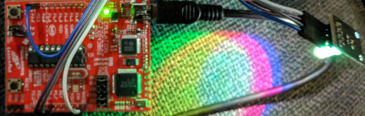
“Common-Cathode” LEDs let you control a red, green, and blue LED individually using PWM signals. Each LED is connected to the same cathode (‘ground’).
This post’s Github repository contains two projects; one which dims and brightens a single on-board LED using PWM, and one which uses a timer interrupt to pulse each color in a common-cathode RGB LED while putting the device to sleep when it is not active.
“Bare Metal” MSP430 Programming: Learning About a New Microcontroller
Most of the embedded programming that I’ve written about so far has focused on the STM32 family of ARM microcontrollers produced by ST Microelectronics. Those are a reasonable starting point for learning about microcontrollers, because they have a solid suite of open-source development tools, a decade-long history of popular use, and affordable hardware development tools which let you get started for less than $20.
But now that platforms like Arduino have become popular and presumably profitable, more vendors are getting on board with providing affordable “DIY” development tools. So while I couldn’t find any cheap and widely-available USB debuggers for TI’s MSP430 core, the “Launchpad” boards that they sell each include an on-board debugger which they say can talk to most MSP430 chips through a two-wire interface similar to the “Serial-Wire Debug” protocol used by a number of Mobile ARM cores including the STM32.
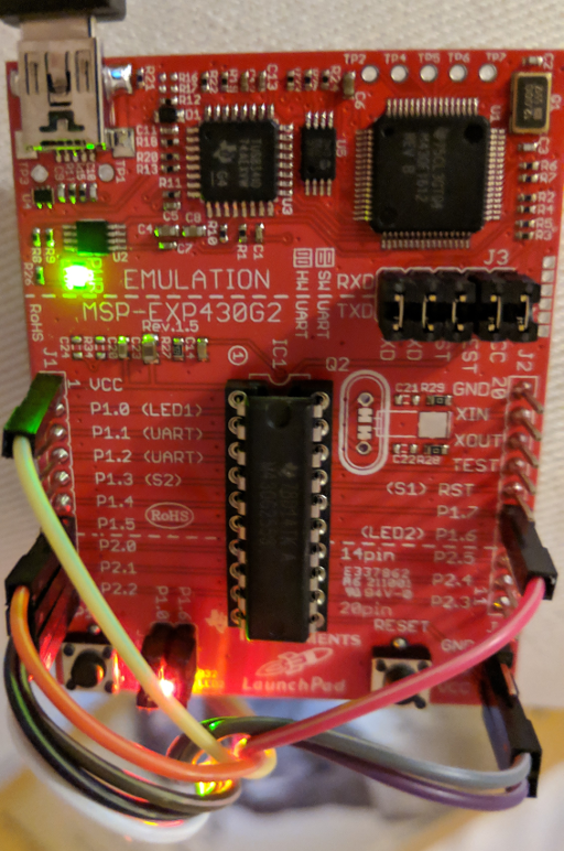
Like the Arduino Uno, some Launchpad boards use DIP chips which you can remove and plug into a breadboard once they have been programmed.
So let’s learn how to write bare-metal programs for the MSP430! This will be easier than bootstrapping a build system for the STM32, because TI opted to design a special-purpose 16-bit RISC core for these chips instead of buying a cookie-cutter core from ARM. That means that the MSP430-GCC toolchain can include ‘glue’ code like linker scripts and vector tables for every MSP430 chip ever made, and we will not need to write our own. There are also fewer steps involved in setting up clocks and peripherals, so this is a comparatively easy platform to develop on. And as usual, this tutorial’s code is on Github.