
Random
Simple USB / Serial Communication with the CP2102N
Several years ago, a company called Future Technology Devices International (FTDI) sold what may have been the most popular USB / Serial converter on the market at the time, called the FT232R. But this post is not about the FT232R, because that chip is now known for its sordid history. Year after year, FTDI enjoyed their successful chip’s market position – some would say that they rested too long on their laurels without innovating or reducing prices. Eventually, small microcontrollers advanced to the point where it was possible to program a cheap MCU to identify itself as an FT232R chip and do the same work, so a number of manufacturers with questionable ethics did just that. FTDI took issue with the blatant counterfeiting, but they were unable to resolve their dispute through the legal system to their satisfaction, possibly because most of the counterfeiters were overseas and difficult to definitively trace down. Eventually, they had the bright idea of publishing a driver update which caused the counterfeit chips to stop working when they were plugged into a machine with the newest drivers.
FTDI may have technically been within their rights to do that, but it turned out to be a mistake as far as the market was concerned – as a business case study, this shows why you should not target your customers in retaliation for the actions of a 3rd party. Not many of FTDI’s customers were aware that they had counterfeit chips in their supply lines – many companies don’t even do their own purchasing of individual components – so companies around the world started to get unexpected angry calls from customers whose toy/media device/etc mysteriously stopped working after being plugged into a Windows machine. You might say that this (and the ensuing returns) left a bad taste in their mouths, so while FTDI has since recanted, a large vacuum opened up in the USB / Serial converter market almost overnight.
Okay, that might be a bit of a dramatized and biased take, but I don’t like it when companies abuse their market positions. Chips like the CH340 and CH330 were already entering the low end of the market with ultra-affordable and easy-to-assemble solutions, but I haven’t seen them much outside of Chinese boards, possibly due to a lack of multilingual documentation or availability from Western distributors. So at least in the US, the most popular successor to the FT232R seems to have been Silicon Labs’ CP2102N.
It’s nice to have a cheap-and-cheerful way to put a USB plug which speaks UART onto your microcontroller boards, so in this post, I’ll review how to make a simple USB / UART converter using the CP2102N. The chip comes in 20-, 24-, and 28-pin variants – I’ll use the 24-pin one because it’s smaller than the 28-pin one and the 20-pin one looks like it has some weird corner pads that might be hard to solder. We’ll end up with a simple, small board that you can plug into a USB port to talk UART:
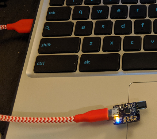
Drivers for the CP2102N are included in most popular OSes these days, including Linux distributions, so it’s mostly plug-and-play.
It’s worth noting that you can buy minimal CP2102N boards from AliExpress or TaoBao for about $1, but where’s the fun in that?
New 8-pin ARM Core: the STM32G031J6
It has been about nine months since ST released their new STM32G0 line of microcontrollers to ordinary people like us, and recently they released some new chips in the same linup. It sounds like ST wants this new line of chips to compete with smaller 8-bit micros such as Microchip’s venerable AVR cores, and for that market, their first round of STM32G071xB chips might be too expensive and/or too difficult to assemble on circuit boards with low dimensional tolerances.
Previously, your best bet for an STM32 to run a low-cost / low-complexity application was probably one of the cheaper STM32F0 or STM32L0 chips, which are offered in 16- and 20-pin TSSOP packages with pins spaced 0.65mm apart. They work great, but they can be difficult to use for rapid prototyping. It’s hard to mill or etch your own circuit board with tight enough tolerances, and it’s not very easy to solder the chips by hand. Plus, the aging STM32F031F6 still costs $0.80 each at quantities of more than 10,000 or so, and that’s pretty expensive for the ultra-cheap microcontroller market.
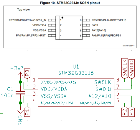
Pinout and minimal circuit for an STM32G031J6 – you only really need one capacitor if you have a stable 3.3V source.
Enter the STM32G031J6: an STM32 chip which comes in a standard SOIC-8 package with 32KB Flash, 8KB RAM, a 64MHz speed limit, and a $0.60 bulk price tag (closer to $1.20-1.40 each if you’re only buying a few). That all compares favorably to small 8-pin AVR chips, and it looks like they might also use a bit less power at the same clock speeds. Power consumption is a tricky topic because it can vary a lot depending on things like how your application uses the chip’s peripherals or what voltage the chip runs off of. But the STM32G0 series claims to use less than 100uA/MHz, and that is significantly less than the 300uA/MHz indicated in the ATTiny datasheets. Also, these are 32-bit chips, so they have a larger address space and they can process more data per instruction than an 8-bit chip can.
Considering how easy STM32 chips are to work with, it seems like a no-brainer, right? So let’s see how easy it is to get set up with one of these chips and blink an LED.
Mounting Solar Panels to a Car
As someone who likes both electronics and the outdoors, sometimes I get anxiety about a lack of electricity. It would be nice to go camping somewhere away from it all, and still be able to charge things and run some lights, a display, maybe a small cooler. I’m sure some of you are rolling your eyes at that, but I’ve also been wanting to play with adding aftermarket indicators to old cars, like backup sensors or blind spot warnings, and it’d be nice to run them off a separate battery to avoid the possibility of accidentally draining the car’s battery overnight.
Since low-power solar panels are fairly cheap these days, I figured that it might be worth buying a few to mount to my car’s roof. And since my car is technically a pickup, it was very easy to put the battery in the bed and run the wiring through the canopy’s front window:
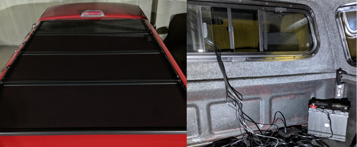
I’ve secured the battery a bit more since taking these pictures, but this is the basic idea – it’s pretty simple.
If you have a different kind of car, I’d imagine that you could just as easily put the battery in your trunk, but you might need to drill a hole for the wires if you don’t want to leave one of your windows cracked open.
I guess that a lot of this guide won’t apply exactly to your situation, because you’ll have different dimensions to work with, different limitations, and probably different solar panels. But I hope that laying out each step that I took and what worked for me might be helpful – your basic approach could probably look very similar.
And before we go any further, please keep your expectations in check. These panels can only produce up to 100W in direct sunlight, which is nowhere near enough power for something like an electric vehicle. So read on if this sounds interesting, but the car still runs on gas. We’re not saving the world here.
Hello, Rust: Blinking LEDs in a New Language
Rust is a fairly new language that has gotten to be very popular in recent years. And as the language matures, it has started to support a wider set of features, including compilation and linking for bare-metal targets. There is an excellent “Embedded Rust” ebook being written which covers the concepts that I’ll talk about here, but it’s still in-progress and there aren’t many turn-key code examples after the first couple of chapters.
The Rust language is less than 10 years old and still evolving, so some features which might change in the future are only available on the nightly branch at the time of writing; this post is written for rustc version 1.36. And the language’s documentation is very good, but it can also be a little bit scattered in these early days. For example, after I had written most of this post I found a more comprehensive “Discovery ebook” which covers hardware examples for an STM32F3 “Discovery Kit” board. That looks like a terrific resource if you want to learn how to use the bare-metal Rust libraries from someone who actually knows what they’re talking about.
As a new Rustacean, I’ll admit that the syntax feels little bit frustrating at times. But that’s normal when you learn a new language, and Rust is definitely growing on me as I learn more about its aspirations for embedded development. Cargo looks promising for distributing things like register definitions, HALs, and BSPs. And there’s an automated svd2rust utility for generating your own register access libraries from vendor-supplied SVD files, which is useful in a language that hasn’t had time to build up an extensive set of well-proven libraries. So in this post I’ll talk about how to generate a “Peripheral Access Crate” for a simple STM32L031K6 chip, and how to use that crate to blink an LED.

It’s kind of fun when languages have mascots, especially when they’re CC0-licensed.
The target hardware will be an STM32L031K6 Nucleo-32 board, but this should work with any STM32L0x1 chip. I also tried the same process with an STM32F042 board and the STM32F0x2 SVD file, which worked fine. It’s amazing how easy it is to get started with a new chip compared to C, although you do still need to read the reference manuals to figure out which registers and bits you need to modify. This post will assume that you know a little bit about how to use Rust, but only the very basics – I’m still new to the language and I don’t think I would do a good job of explaining anything. The free Rust ebook is an excellent introduction, if you need a quick introduction.
Using Tabula to Parse PDF Tables
Recently, I wrote about trying to figure out a way to automatically produce visualizations of STM32 peripheral mappings from their datasheets. Unfortunately, it didn’t go too well; I had trouble parsing the output from the command-line pdftotext utility, so I ended up having to manually clean up each peripheral table after it was half-parsed by a script.
I was thinking of trying to write a better parsing script, but before diving into that rabbit hole I took another look at open-source PDF-parsing programs and found Tabula. It is an MIT-licensed utility with one goal: extracting tables from PDF files. And it seems to work very well with ST’s datasheets.
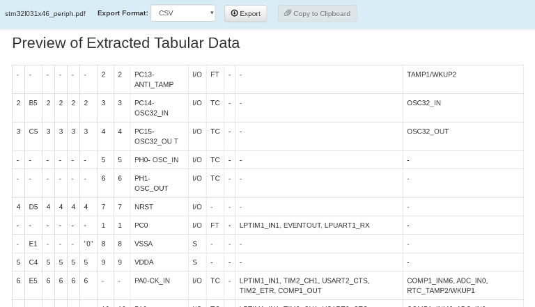
Tabula has a nice local web interface which gives you previews of the table data that it will export from a PDF.
Step 1: Download Tabula
Tabula runs on Java, so it’s simple to set up on just about any platform. They have good installation instructions on their website and GitHub readme file. If you are using Linux, you can download and unzip the tabula-jar-<version>.zip version of the latest release to get a runnable JAR file.
Following the instructions in the README.md file, once you unzip the file and cd into its tabula/ directory, you can start running a local server with the command that the readme file suggests:
java -Dfile.encoding=utf-8 -Xms256M -Xmx1024M -jar tabula.jar
Once it starts up, you should be able to navigate to http://127.0.0.1:8080 in a browser to access the Tabula UI. There is also a command-line version of the project, which will probably be better for setting up an automatic process. But for now, it’s nice to use the visual selection tools which the UI provides.
Making Pretty(ish) Reference Images for Microcontrollers
When you want to pick a microcontroller for a project, it can be useful to have a bunch of quick references to find the smallest/cheapest one that will fit the parts you want to use. Usually the information is freely available in datasheets, but those are usually PDF files with pinout/peripheral information spanning several pages.
So I’ve been playing with ways to partially automate the process of generating some nice reference images. I’m not exactly happy with what I have yet, but it’s not the sort of thing that merits spending a ton of time on, and I think I scripted away enough of the tedium that it isn’t too frustrating to make these sorts of tables. You wind up with reference images like this:
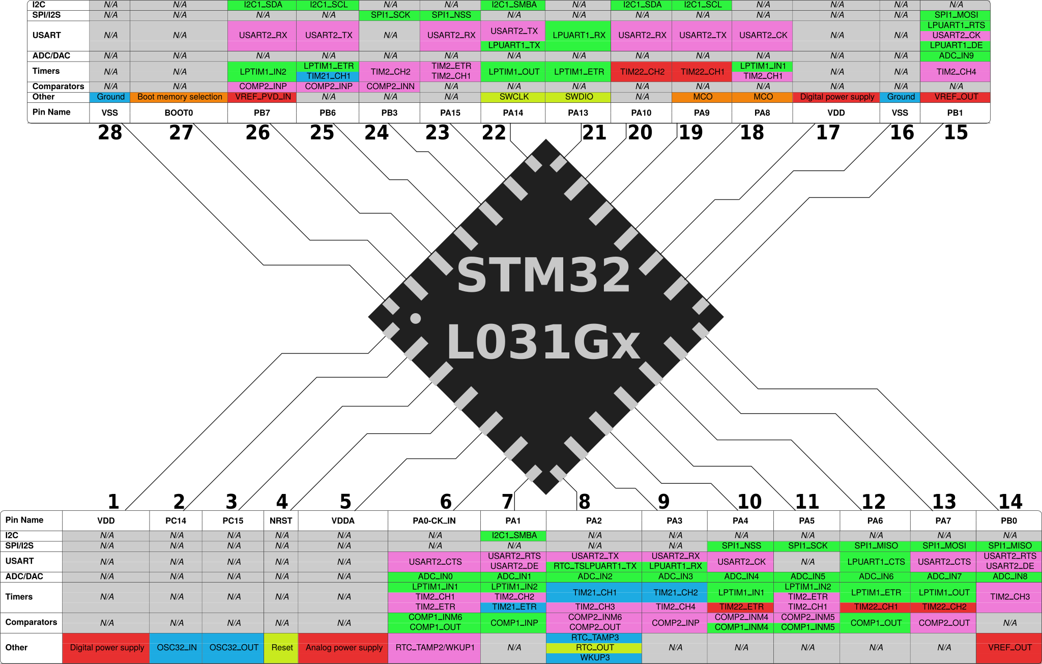
STM32L031Gx Pinout / Peripherals
Honestly, this post would be sort of moot if I could find nice CSV files or spreadsheets of STM32 pinouts and peripherals (see below). Maybe other vendors distribute information in that format, but I couldn’t find many for ST’s chips. And that means that I ended up with a sort of convoluted process.
A fragile Python script runs the pdftotext utility to convert an STM32 datasheet into a pinout table containing peripheral information. The automatic formatting doesn’t include table cell boundaries, so I couldn’t figure out how to put all of the peripherals associated with a pin on the same line quickly; someone needs to manually perform that step before running a second Python script which generates LaTeX files representing formatted peripheral tables. The PDF files generated by pdflatex can then be imported into Inkscape, where the table columns can be connected to the pins on an image of the chip’s outline. So, let’s get started!
Note: I ended up finding a better way to parse STM32 datasheets using a project called Tabula – see this newer post for more information. My first attempt presented in this post ended up working pretty poorly, but that’s life for you. Sometimes it takes a few tries to find a good solution.
Getting Started with Bare Metal ESP32 Programming
The ESP32 modules sold by Espressif are very popular in the IoT and embedded development space. They are very cheap, they are quite fast, they include radios and peripherals for WiFi and Bluetooth communication, and in some ways they even appear to bridge the gap between MCU and CPU. And Espressif provides pre-built modules with built-in antennas and external Flash memory, both of which appear to be required for general-purpose ‘IoT’ application development. They can be a bit power-hungry when they are using their wireless communication modules though, and I haven’t found much information on how to develop ESP32 applications without using the heavyweight (but very functional and well-written) “ESP-IDF” toolchain which is distributed by Espressif.
Usually, avoiding bulky and proprietary HALs is a worthwhile goal in and of itself. But Espressif has actually released their ESP-IDF toolchain under a very permissive Apache license, and it looks like a well-thought-out system with solid ongoing support. So if you are looking at starting a new project with the ESP32, I would personally recommend using the ESP-IDF to save time and effort. But sometimes it is nice to learn about how chips work at a deeper level, and ESP-IDF projects are often quite large, and they can take a long time to build depending on your environment.
The large code size also discourages what appears to be one use case that the chip was designed for: to load new instructions into RAM every time that it reboots from an external ‘socket’. The current crop of ESP32 modules use a SPI Flash chip as that ‘socket’, but if you put them in a factory or a field you might want to use Ethernet, or RS-232, or who knows what. I’m not sure how extensible the chip’s ROM bootloader actually is yet, but let’s take a look at what it takes to get a simple C program running on the ESP32 without using the ESP-IDF build system.
Unlike the STM32 and MSP430 microcontrollers which I have written about previously, there are not many software tools available for the ESP32 core. The ESP32’s dual-core architecture uses two ‘Xtensa LX6’ CPU cores which Espressif licenses from Cadence, and I haven’t seen them in any other mainstream microcontrollers. It looks like a core that is intended to be customized for the needs of an application as a step between general-purpose microcontrollers and something like an ASIC, so maybe it is more common in application-specific environments than general-purpose ones. In this case, it looks like the specific application which Espressif chose is wireless communication, and apparently a lot of the WiFi and Bluetooth code is burned directly into the ESP32’s ROM.
The ESP32 also looks more like a proper CPU than many microcontroller cores, with a few hundred kilobytes of on-chip RAM, a 240MHz top speed, an MMU, and support for up to 8 process IDs (2 privileged / 6 unprivileged) per core. People used to make do with much less, but since the ESP32 is complex and somewhat unique, Espressif provides the only toolchain that I know about which can build code for it. That means that while this tutorial will not use the full ESP-IDF development environment, it will still use Espressif’s ports of GCC and OpenOCD for compilation and debugging, as well as their esptool utility for formatting and flashing the compiled code. The target hardware will be either the ESP32-WROVER-KIT board which includes a JTAG debugging chip, or any of the smaller generic ESP32 dev boards (such as the ESP32-DevKitC) combined with an FTDI C232HM cable.
And like most of my previous tutorials, the software presented here is all open-source and you should be able to build and run it on the platform of your choice. It won’t have any colorful LEDs this time – sorry – but the code is available on GitHub. I’m also still learning about this chip and there is a lot that I don’t know, so corrections and comments are definitely appreciated. So if you’re still interested after those disclaimers, let’s get started by building and installing the toolchain!
Building a Bare-Metal ARM GCC Toolchain from Source
The GCC toolchain is a nice way to get started with bare-metal ARM platforms because it is free, well-supported, and something that many C programmers are already familiar with. It is also constantly improving, and while most Linux distributions include a version of the arm-none-eabi GCC toolchain in their default package managers, those versions are sometimes old enough that I run into bugs with things like multilib/multiarch support.
So after trying and failing a few times to build and install this toolchain, I thought I would share what eventually worked for me. If you are building this on a system without much free disk space, this did take about 16GB of disk space when I ran it – but you shouldn’t need to keep more than ~500MB of that. I ended up building it on an ext3-formatted 32GB USB drive, and that seemed to work fine. You will probably run into errors if you try to run this on a FAT-formatted drive like a new USB stick, though, because the build process will run chmod and that will fail on a filesystem that doesn’t support file permissions. You might be able to make it work with an NTFS drive, but I digress.
Anyways, the first step is downloading the code, so let’s get started!
Step 1: Download the Source Code
The first step is to download the arm-none-eabi-gcc source code from ARM’s website – you want the “Source Invariant” version. If you are using a common architecture such as x86_64, you can also download a pre-built version of the latest release, but you probably want to build the thing yourself if you are reading this guide. If you want to make sure that the file you downloaded was not corrupted or tampered with, you can check it against the MD5 checksum listed under the file’s name on the download page:
> md5sum gcc-arm-none-eabi-8-2018-q4-major-src.tar.bz2
d6071d95064819d546fe06c49fb9d481 gcc-arm-none-eabi-8-2018-q4-major-src.tar.bz2
That looks like it matches as of the time of writing. The archive contains build scripts and code for the whole toolchain, so create a new directory to build the toolchain in – I’ll use ~/arm_gcc/ as an example. Once it finishes downloading, move the archive to that folder and extract it:
> mkdir ~/arm_gcc
> cd ~/arm_gcc
> mv [Your_Downloads_Folder]/gcc-arm-none-eabi-8-2018-q4-major-src.tar.bz2 .
> tar -xvf gcc-arm-none-eabi-8-2018-q4-major-src.tar.bz2
The file that I downloaded was called gcc-arm-none-eabi-8-2018-q4-major-src.tar.bz2, but yours will depend on where you are in time. The extracted archive will make a new directory with a similar name – take a look inside, and you’ll see a few scripts and a ‘how-to’ document alongside the source code:
> cd gcc-arm-none-eabi-8-2018-q4-major/
> ls
build-common.sh build-toolchain.sh install-sources.sh python-config.sh release.txt
build-prerequisites.sh How-to-build-toolchain.pdf license.txt readme.txt src
Making a Retro Wall Clock
It’s good to know what time it is, and once you work out how to use a RealTime Clock module, making a clock display seems like a natural next step. 7-segment LED displays used to be the go-to way to display time digitally before LCD and OLED screens got so cheap, and I thought it would be fun to make a more modern take on them with diffused multicolor LEDs for the actual lighting. I would like to write a post about drawing to traditional 7-segment digits using shift registers, but this project uses the easy-to-wire ‘Neopixels’ that we all know and love.
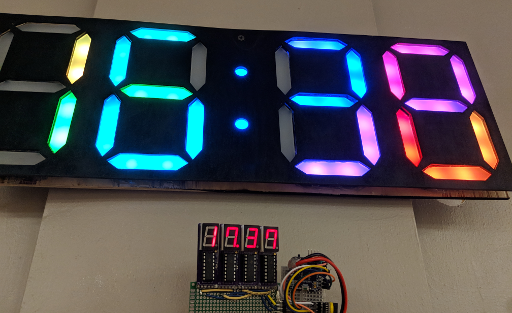
The one on the bottom doesn’t know about daylight savings, but you get the idea.
You’ll need a few materials for this project if you want to follow along:
- Access to a laser cutter and a 3D printer.
- About 6 x 12″ of 1/8″-thick ‘frosted’ acrylic, to diffuse the LEDs. (About 150 x 300mm, 3mm thick)
- Enough plywood to make a clock face for the front and back; I wound up using about 500 x 200mm each.
- 58 individually-addressable RGB LEDs. (28 sets of 2 for each segment of the 4 digits, and 2 more for the colon dots.)
- A DS3231 or similar realtime clock module.
- A microcontroller to run everything; I used an ATMega328 on an “Arduino” nano board to keep the code simple.
- Craft supplies: solder, soldering iron, glue, hot glue gun, wire, etc.
For the LEDs, I cut lengths off of a reel of LED strip that I ordered off Amazon; I think it used SK6812 LEDs and had 30 LEDs / meter. For the two dots of the colon, you can also buy small single-LED boards that are about 10mm in diameter and usually have WS2812B LEDs. I didn’t run into any problems stringing SK6812 and WS2812B LEDs together with Adafruit’s “Neopixel” library, but caveat emptor.
Replacing Broken Car Speakers
Some Cars are Old
Recently, I bought a very used car in the hopes of modifying it to use a parallel-hybrid drivetrain. I’d like to cut the driveshaft and slot an electric motor inline with it, and that will probably be the subject of future posts if I can find a garage willing to do most of the heavy lifting and cutting.
But in the meantime, what sort of car do you get if you’re thinking of cutting its driveshaft in half? A cheap one, of course – and my choices were further limited by a few basic requirements:
- The car should actually be a small pickup truck; the bed is an ideal place to put the heavy batteries, they tend to have a lot of ground clearance for fitting a bulky motor underneath the chassis which means little or no changes to the bodywork, and passenger space is not a consideration in this build.
- It should be rear-wheel drive. Since I am planning to add a motor between the transmission and the differential, there needs to be enough space along the driveshaft to fit the motor. That means either rear-wheel drive with the engine in the front, or front-wheel drive with the engine in the back. And I don’t know of any rear-engine pickup trucks.
- It should have an automatic transmission. This kind of simple conversion leaves you with two acceleration pedals, and I don’t have enough feet to use four pedals at once.
So I wound up with a cheap-and-cheerful 1994 Toyota Pickup Truck. It doesn’t actually have a model name; in North America, the Hilux brand was renamed to “Truck” in the 1970s before eventually being replaced with the Tacoma. So this is not a luxury vehicle. It has roll-up windows, it does not have ABS, it came with a broken speedometer, and more importantly its speakers had disintegrated in the decades since 1994.
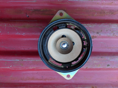
Yikes.
That’s no good, and it sounded like the buzzing of a thousand wasps. Plus, replacing your speakers seems like a pretty easy first project if you want to learn about a car. You only have to remove a few interior panels, and your sound system is a safe thing to break compared to say, your brakes. So let’s get started! These specific instructions may be for a 1994 Toyota pickup, but I’ll bet the process looks similar for the front speakers of other cars.
Recycling HDPE: What Doesn’t Work
Over the past month or two, I’ve been learning about plastic recycling with a friend at a local makerspace. We decided to start out with HDPE as a nice beginner’s material, because it melts at less than 200C and tends to be fairly nontoxic. We’ve tried a few different techniques now, and we’ve learned a lot about what doesn’t work.
This is an exciting field and we hope to make a decent press for forming 3mm and 6mm-thick HDPE sheets soon, but our early designs have shown us some key difficulties to be aware of if you are planning to start recycling plastics on your own. And I’ll mention this later, but please research what you plan to recycle ahead of time and avoid plastics which might release hazardous fumes. As you will see, I am not an expert.
Our first instinct was to imitate an injection-molding press, and we started by scavenging some large heating elements from a Goodwill-sourced griddle. It consisted of four ~13-Ohm coils arranged as two parallel banks, each consisting of two elements in series. That meant an effective resistance of 13 Ohms, or a bit over 9 amps at the mains 120V which it was more or less directly connected to.
We wound up clipping the heating coils out and scavenging some of the crimped and heat-insulated wiring, strapping them to a smooth-bore metal pipe, and then soldering or spot-welding the four coils back together in their original 2×2 arrangement. Temperature monitoring is all well and good, but this was a first attempt; we just wired the coils across a 2-prong plug, and flipped a surge suppressor on and off to control the heat. A handheld infrared thermometer gave us a rough indication of the tube’s temperature, and we aimed for 350-400F to melt the HDPE.
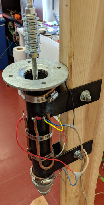
Our first attempt at a plastic-melting tube; the heating elements are the thick copper-coated wires, and the beige wires connect directly to a 2-prong wall plug.
The W1209: A (sometimes) STM8-based digital thermostat
Among the cheap gadgetry that constantly spews forth from the spawning pits of consumer electronics, sometimes you can find a gem. The W1209 is an interesting board which is designed to act as a thermostat which can also switch a relay when certain temperatures are reached. It is used in everything from rice cookers to yogurt machines to people who want their A/C to only turn on when it’s hot out. Originally they shipped with an aging but fairly capable STM8S003F3 microcontroller, and they cost less than $1.50 each.
Even so, their popularity has inspired the usual imperfect cloning process, so chances are that a board you buy from ebay, Aliexpress, Taobao, or Amazon today will need some touching up before you will be able to reprogram it. In this tutorial, we will replace the microcontroller and add a few missing capacitor/resistors. Then we’ll upload a simple test program to test that the microcontroller and board both work. So here is an example of what is probably the worst possible knock-off that you could fear to get, with missing or faulty parts highlighted:
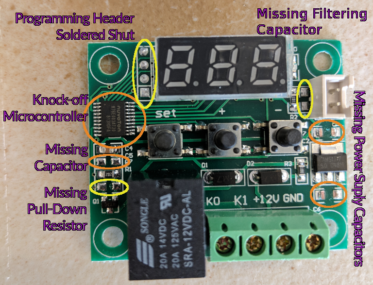
W1209 that needs fixing
Well, that’s life. You try your best, and then someone comes along and kicks you in the teeth. But let’s make some lemonade and take the opportunity to learn about fixing cheap-o knock-off circuit boards!