
Several years ago, a company called Future Technology Devices International (FTDI) sold what may have been the most popular USB / Serial converter on the market at the time, called the FT232R. But this post is not about the FT232R, because that chip is now known for its sordid history. Year after year, FTDI enjoyed their successful chip’s market position – some would say that they rested too long on their laurels without innovating or reducing prices. Eventually, small microcontrollers advanced to the point where it was possible to program a cheap MCU to identify itself as an FT232R chip and do the same work, so a number of manufacturers with questionable ethics did just that. FTDI took issue with the blatant counterfeiting, but they were unable to resolve their dispute through the legal system to their satisfaction, possibly because most of the counterfeiters were overseas and difficult to definitively trace down. Eventually, they had the bright idea of publishing a driver update which caused the counterfeit chips to stop working when they were plugged into a machine with the newest drivers.
FTDI may have technically been within their rights to do that, but it turned out to be a mistake as far as the market was concerned – as a business case study, this shows why you should not target your customers in retaliation for the actions of a 3rd party. Not many of FTDI’s customers were aware that they had counterfeit chips in their supply lines – many companies don’t even do their own purchasing of individual components – so companies around the world started to get unexpected angry calls from customers whose toy/media device/etc mysteriously stopped working after being plugged into a Windows machine. You might say that this (and the ensuing returns) left a bad taste in their mouths, so while FTDI has since recanted, a large vacuum opened up in the USB / Serial converter market almost overnight.
Okay, that might be a bit of a dramatized and biased take, but I don’t like it when companies abuse their market positions. Chips like the CH340 and CH330 were already entering the low end of the market with ultra-affordable and easy-to-assemble solutions, but I haven’t seen them much outside of Chinese boards, possibly due to a lack of multilingual documentation or availability from Western distributors. So at least in the US, the most popular successor to the FT232R seems to have been Silicon Labs’ CP2102N.
It’s nice to have a cheap-and-cheerful way to put a USB plug which speaks UART onto your microcontroller boards, so in this post, I’ll review how to make a simple USB / UART converter using the CP2102N. The chip comes in 20-, 24-, and 28-pin variants – I’ll use the 24-pin one because it’s smaller than the 28-pin one and the 20-pin one looks like it has some weird corner pads that might be hard to solder. We’ll end up with a simple, small board that you can plug into a USB port to talk UART:
Drivers for the CP2102N are included in most popular OSes these days, including Linux distributions, so it’s mostly plug-and-play.
It’s worth noting that you can buy minimal CP2102N boards from AliExpress or TaoBao for about $1, but where’s the fun in that?
Schematic
A basic schematic for the 24-pin version of this chip is pretty simple; I attached LEDs to the GPIO1 and GPIO2 pins, since those can be configured to pulse when ‘transmit’ and ‘receive’ traffic is ongoing. But otherwise, it’s only a matter of implementing the recommendations found in the chip’s datasheet. It’s even got a built-in 3.3V regulator! Here’s the schematic that I wound up with, but you can also find a full KiCAD project in this board’s GitHub repository.
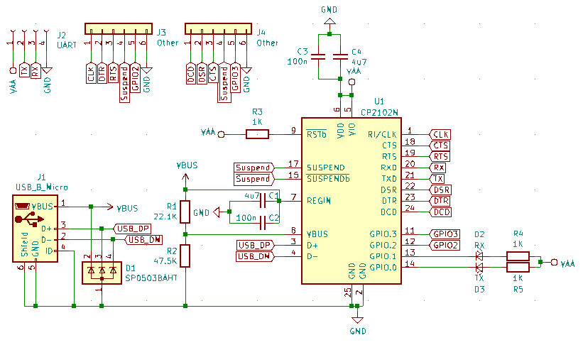
Super-simple CP2102N Schematic. Sometimes I’ll follow the convention which uses an SI prefix instead of a decimal point to save space, so the capacitors marked “4u7” are 4.7 microFarads.
I don’t usually use most of the USART signals besides TX and RX, but I set aside a couple of ‘other’ headers connected to those pins in case I ever come across a project that requires them. The SP0503BAHT TVS diode array seems like a fairly standard part for protecting USB data/power lines, which is good to know about. There are also versions with different numbers of diodes; an SP0502 part has 3 pins with 2 diodes instead of 4 pins with 3 diodes.
Board Layout
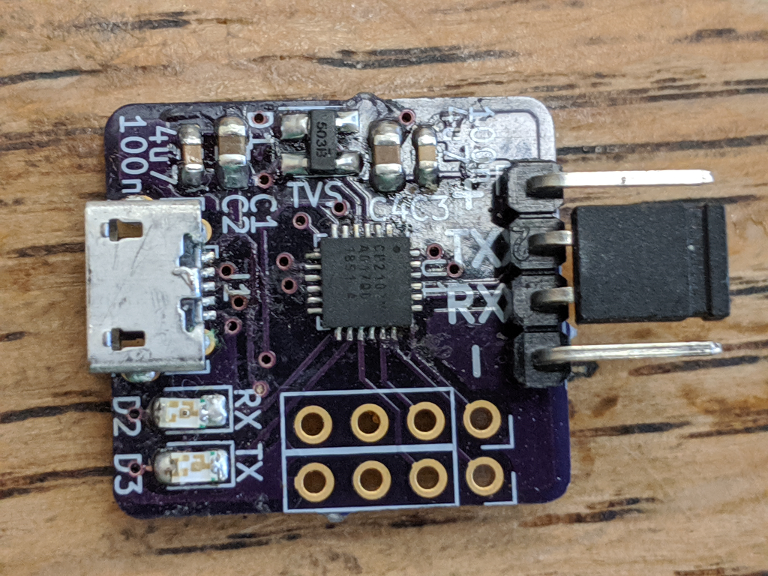
There aren’t really any special considerations for designing a PCB around this chip. The trickiest part is that it has an exposed pad on the bottom, which must be connected to ground. If you’re hand-soldering the chip, you should add a large plated via (>=1mm diameter) over the thermal pad connection so that you can melt solder into the hole from the back of the board. The board’s GitHub repository has the footprint which I used, as an example.
It’s a good idea to use thicker traces (>=0.5mm) for power connections, but otherwise you should be able to stuff this board into a pretty small area. I won’t go over the steps in detail, since that would duplicate a lot of what I’ve written previously, but you can check this board’s GitHub repository to see what I ended up with. Still, why not design your own? If you didn’t include the extra two extra headers with the full USART signals, you could probably slim it down a bit.
Configuration and Testing
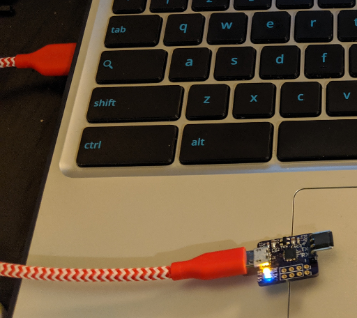
Once your boards arrive and you assemble them, the chip should work as soon as you plug it in. An easy way to test these converters is to connect a jumper between the TX and RX pins, and connect to the serial port which shows up when you plug the board into your computer. With the ‘transmit’ and ‘receive’ pins connected, you should be able to type into the terminal and see your keystrokes echoed back. If you don’t have a favorite program for connecting to a serial port, screen can actually do the job, for example: screen /dev/ttyUSB0 9600. It’s a little tricky to close the connection, though; you have to hit ctrl+a followed by \, then y. So…hopefully you already have a favorite program for connecting to a serial port?
You can test the board quickly by shorting the ‘transmit’ and ‘receive’ pins, then typing into a terminal on a computer that it is plugged into.
The ‘transmit’ and ‘receive’ LEDs probably won’t work when you first assemble the board, though. You need to configure the chip to assign specific functions to its GPIO pins, and while you can get the chips programmed at the factory if you’re a big customer, I am not a big customer. Fortunately, it’s easy to do this yourself with software that the manufacturer provides without cost. The easiest way to configure one of these chips is to download Simplicity Studio, and use its “Xpress Configurator” utility. As long as the board is plugged into your computer’s USB port, it should be easy to use the graphical interface to set up the chip’s GPIO pins and other settings.
Conclusions
The CP2102N is a nice and easy chip to integrate into your designs, and USB / UART bridges are fairly common requirements for projects using chips that lack a USB peripheral. And even when you have a USB peripheral, it’s still nice that you don’t need to mess around with drivers or vendor / hardware IDs if you use one of these chips.
I dunno, sometimes it seems like the best parts are the ones that sound really simple and boring when you describe them. Boring and predictable is good, when you’re talking about designing electronics. Anyways, here’s the GitHub repository with the board that I ended up with after following the above steps. I’m still waiting to receive this new revision of the board, but it is very similar to the one shown in this post’s pictures.


Steve
July 14, 2020 at 5:58 pm
Thanks for this.
Are the TX and RX LEDs the only thing you need Simplicity Studio for? Will it otherwise work without customization?
Vivonomicon
July 26, 2020 at 1:00 pm
I think so; you should be able to omit the LEDs and use the chips as-is.
Joseph
July 31, 2020 at 9:32 am
I did a similar project. My test script worked without any action other than installing the driver on my machine and plugging in the USB cable.