
It’s good to know what time it is, and once you work out how to use a RealTime Clock module, making a clock display seems like a natural next step. 7-segment LED displays used to be the go-to way to display time digitally before LCD and OLED screens got so cheap, and I thought it would be fun to make a more modern take on them with diffused multicolor LEDs for the actual lighting. I would like to write a post about drawing to traditional 7-segment digits using shift registers, but this project uses the easy-to-wire ‘Neopixels’ that we all know and love.
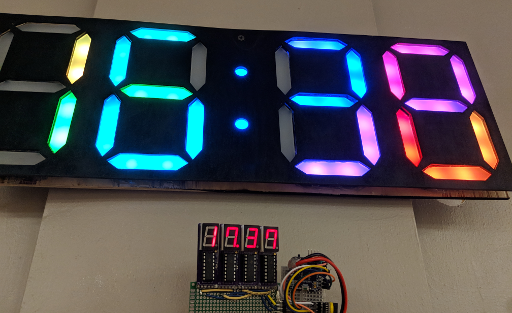
The one on the bottom doesn’t know about daylight savings, but you get the idea.
You’ll need a few materials for this project if you want to follow along:
- Access to a laser cutter and a 3D printer.
- About 6 x 12″ of 1/8″-thick ‘frosted’ acrylic, to diffuse the LEDs. (About 150 x 300mm, 3mm thick)
- Enough plywood to make a clock face for the front and back; I wound up using about 500 x 200mm each.
- 58 individually-addressable RGB LEDs. (28 sets of 2 for each segment of the 4 digits, and 2 more for the colon dots.)
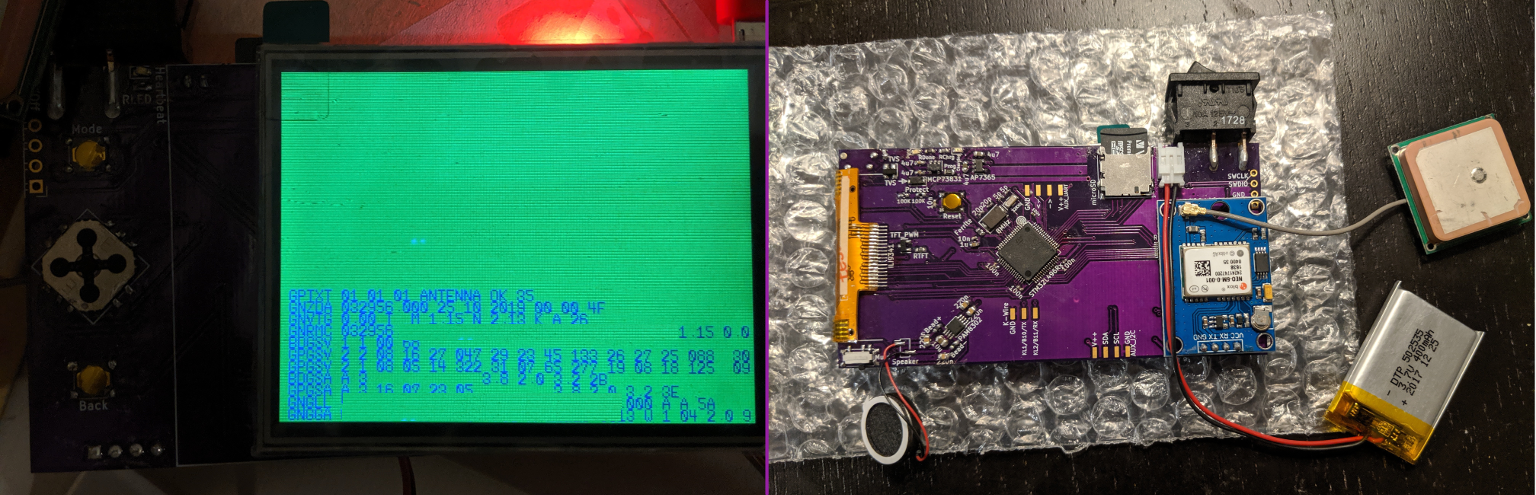
- A DS3231 or similar realtime clock module.
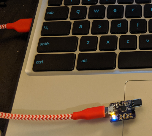
- A microcontroller to run everything; I used an ATMega328 on an “Arduino” nano board to keep the code simple.
- Craft supplies: solder, soldering iron, glue, hot glue gun, wire, etc.
For the LEDs, I cut lengths off of a reel of LED strip that I ordered off Amazon; I think it used SK6812 LEDs and had 30 LEDs / meter. For the two dots of the colon, you can also buy small single-LED boards that are about 10mm in diameter and usually have WS2812B LEDs. I didn’t run into any problems stringing SK6812 and WS2812B LEDs together with Adafruit’s “Neopixel” library, but caveat emptor.
Laser-Cut Parts
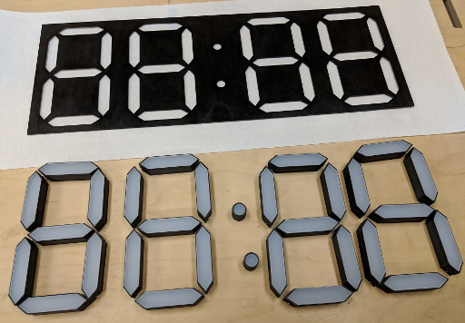
The fastest parts to make are the laser-cut ones. I cut some plywood for the front and rear faces to hold the digits in place, and some diffuse semi-opaque acrylic for the digits themselves. The acrylic panels sit on top of 3D-printed “cells” which we’ll make in the next section, and they are shaped to look like the long hexagonal segments used in many 7-segment displays:
I cut the segments to fit two LEDs in a strip with 30 LEDs per meter.
Unfortunately, I didn’t get the math for the plywood outlines quite right; the 3D-printed walls added a few millimeters to the acrylic panels’ edges, I didn’t take the laser’s kerf into account, and I wound up with outlines that didn’t fit very well. So here is a .SVG file with a cut pattern for 28 the digit segments in the dimensions I used, and I’ll leave the clock face arrangement as an exercise to the reader:
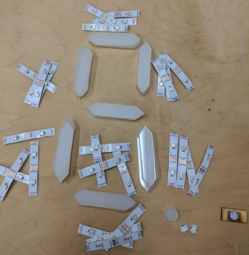
The two dots for the colon were just 14mm-diameter acrylic circles with cylindrical 3D-printed cells to hold the single LED below them. I used a 5.5″ x 12″ cut of acrylic and had just enough for the digit segments and a few small circles, so you should be able to make do with about half a square foot. With everything cut out, you should wind up with parts that look something like this:
Laser-cut parts – the plywood face fits over the digit segments, which also slot into a base with the same pattern. We’ll print the plastic stand-offs underneath each segment in the next section.
I spray-painted the front face black to accentuate the LED colors, and I also cut an extra clock face to give the clock a flat backside for mounting. With both a front and back plane, the 3D-printed segment holders can be fixed in place along the digits’ faces and their bases and the clock can be easily mounted to a wall.
3D-Printed Parts
With the flat materials cut out, it’s time to print out small plastic ‘cells’ to make sure that each segment’s LEDs only light up that one segment, and to keep the LEDs far enough away from the acrylic to diffuse the light. The idea is to have opaque walls with small slits near the segment ‘points’ to slide the LED strips and wires through after they are soldered. You can find the .scad files that I used on Github (and render .stl files with OpenSCAD), or design your own.
You will probably need to add some support material for the slits, since they are 90-degree overhangs in my models and 3D printers don’t handle that very well. These will be hidden by the front face and acrylic panels in the final construction though, so they don’t need to be pretty. The 3.5mm-tall gaps worked fairly well for me, but they were a little tight with some of my blobbier solder joints so you may want to make them a little bit taller. I started by printing one segment at a time until I was happy with the dimensions, and then I printed 7 at once for each digit:
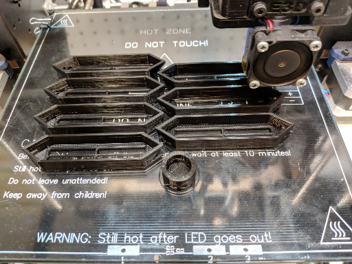
zzzzzz…
This will take a little while; each cell took about 25 minutes to print on a Mendel, which comes out to about 12 hours once you add the two middle dots. So you might want to send off to somewhere like Shapeways if you don’t want to spend hours watching plastic dry, but you could also use it as an opportunity to finally get through that book you’ve been meaning to finish.
Wiring
Once the housing’s parts are all ready, it’s time to connect the LEDs and fit everything together. This part is also sort of tedious, because you need to solder about sixty 3-pin LED connections. I recommend using flexible hookup wire so that you don’t have to measure the lengths very precisely. If your wire is too rigid, it can be difficult to arrange the segments into the shape of your clock digits once everything is soldered together. Flexible wire like silicone-sheathed stranded-core is much easier to bunch up and fit around corners.
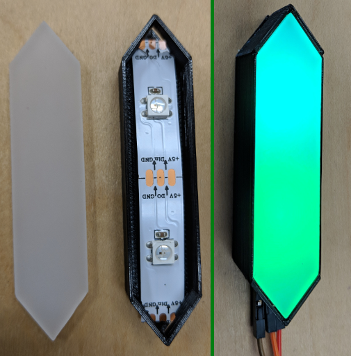
I like this diffusing acrylic already! But you can imagine how this assembly might not be fun to solder.
So simply slide LED strips into each of your 3D-printed cells, fit them into the holes that you cut in your rear clock panel, and then cut lengths of wire for the power, data, and ground lines between each segment. Once you have the lengths of wires it seems easiest to remove the LED strips, solder them together, and then slide the 3D-printed cells down the string one-by-one. And be sure to test that all of the LEDs light up before you glue anything in place or permanently cover the wires; when you accidentally botch a connection halfway through the string, every strand downstream from the mistake will stop working.
Once every LED strip is lighting up inside of its 3D-printed housing, you can start arranging the segments back into your rear clock face’s digit holes. If you measured the wires well, it shouldn’t be too difficult to fit everything back in place. If you made the wires slightly too long like I did, it should still work but the cells might push away from each other until you glue everything together.
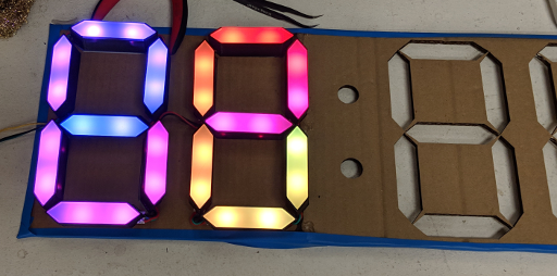
LED wiring in progress. I used a cardboard blank for measuring how long the wires should be, and I finished assembling each digit before moving on to the next.
The strips are wired in a single line. It starts at the left side of the center segment, then loops around through the upper-right, top, upper-left, bottom-left, bottom, and bottom-right segments. Then it continues out of the top of the bottom-right segment to the next digit. you can wire things differently, but that’s how my example code assumes they will be arranged.
Assembly
With every individual part connected and working, it’s time to permanently assemble the display. It would be nice to make a removable housing with screws or hinges, but this was a first attempt so I just hot-glued each segment to both the rear and front faces on the inside. I recommend hot-gluing over the LED strip connections too, once you are sure that they all work. It will help prevent them from flexing and shorting together, which is good because you will have trouble repairing any of the connections once the whole piece is all glued together.
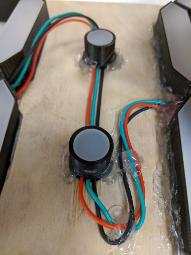
Glued-on segments
Once I had glued all of the segments in place, I picked up the display to hold it against the wall, and the acrylic panels spilled all over the floor. They didn’t quite press-fit into their 3D-printed housings, so I needed to glue them on as well. You might get some visible blobs if you use too much glue, so I recommend placing a small bead of hot glue at each corner of the plastic shell, and then quickly pressing the acrylic section into place before they dry. Cyanoacrylate or acrylic cement may also work, but they are much less viscous so you’d have to be careful not to let them spread over the acrylic faces.
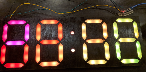
After that I hot-glued the plywood front face on in the same way as the rear one, which made the display rugged enough to carry around and occasionally bump against things. I did need to carefully cut away some glue blobs where the hot glue seeped through the spaces between the segments and the front face of the display, but you might not need to do that if you measure your cuts more accurately than I did. About a dozen hot glue sticks later, I ended up with a working display panel:
Great! But this isn’t actually a clock until it shows the time.
The Code
All that remained was to make the display show the current time, instead of ’88:88′. I had been working on this all weekend and wanted to get something working, so I just used Arduino libraries for the realtime clock module and LEDs. The program logic basically just runs the ‘rainbow cycle’ effect from Adafruit’s ‘strand test’ example program, but before it sends any colors to the LEDs, it reads the clock module and turns off any segments that are not needed to show the current time.
You can find the full Arduino sketch on Github. You’ll need to install two libraries in the Arduino IDE: ‘Adafruit_NeoPixel’ by Adafruit, and ‘RTCLib’ by Jeelab. I haven’t written a way to change the time yet, but RTCLib will automatically set the time to whenever the program was compiled if it detects that the DS3231 module lost power. So you can reset the time by removing the module’s backup battery while it is unplugged, re-compiling and uploading the program, then re-inserting the battery before unplugging everything.
Anyways, the result looks quite nice:
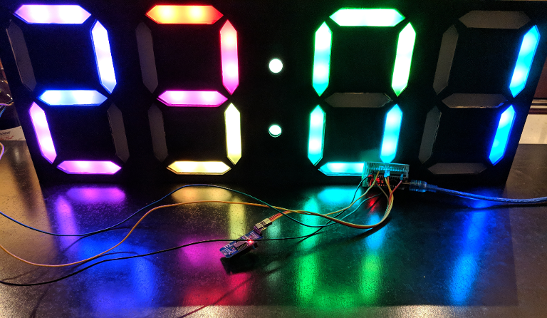
Usually my finished projects look terrible unless you’re into circuit-chic, but colorful LEDs are the new black.
Conclusions
This was actually a gift for a local makerspace; they’ve been talking about getting a wall clock for a few months. And it demonstrates how you can apply a few of the tools that makerspaces provide access to: laser cutters, 3D printers, pretty colored lights, all that jazz.
But it also made me appreciate how easy it has gotten to prototype simple ideas lately – it’s not an exaggeration to say that the code for this project took less than an hour to write, thanks entirely to organizations like Adafruit, Arduino and the communities that sprang up around them. So as fun as it is to learn about how things work in detail, it’s also amazing how much you can accomplish without needing to dig very deeply at all.
Anyways, I think this project turned out reasonably well, but I’d love to hear about it if you build your own and/or think of a faster way to make a display like this!