
If you choose to pursue embedded development beyond the occasional toy project, it probably won’t take long before you want to design something which runs off of battery power. Many types of devices would not be useful if they had to be plugged into a wall outlet all the time, and power efficiency is one of the biggest advantages that microcontrollers still have over application processors like the one in a Raspberry Pi.
When you do move an application to battery power, you’ll quickly discover that it is very important for your device to be able to A) charge its battery and B) alert you when its battery is running low. Not knowing whether something has hours or seconds of life left can be really annoying, and trying to use a nearly-dead battery can cause strange behavior, especially if the battery’s power drops off slowly as it dies. Most lithium-based batteries also last longer if you avoid fully discharging them – there’s some good information about lithium battery aging in this article.
So in this post, I’m going to go over a very basic circuit to power an STM32 board off of a single lithium-ion battery and monitor its state of charge. I will also talk briefly about how to add a simple battery charger to your design, but you should always independently verify any circuitry which interacts with lithium batteries! This circuit seems to work to the best of my knowledge, but don’t take my word for it; it’s very important to double- and triple-check your li-po battery circuits, because they can easily become serious fire hazards if they are handled improperly. It’s also good practice to avoid leaving lithium-ion batteries unattended while they are charging, and you should try to get batteries with built-in protection circuitry to help mitigate bad situations like over-current, under-voltage, etc.
So with those brief and not comprehensive safety warnings out of the way, let’s get started! I’ll use an STM32L4 chip for this example, but the ADC peripheral doesn’t seem to change much across STM32s. And here is a GitHub repository containing design files for a simple board which demonstrates the concepts described in this post.
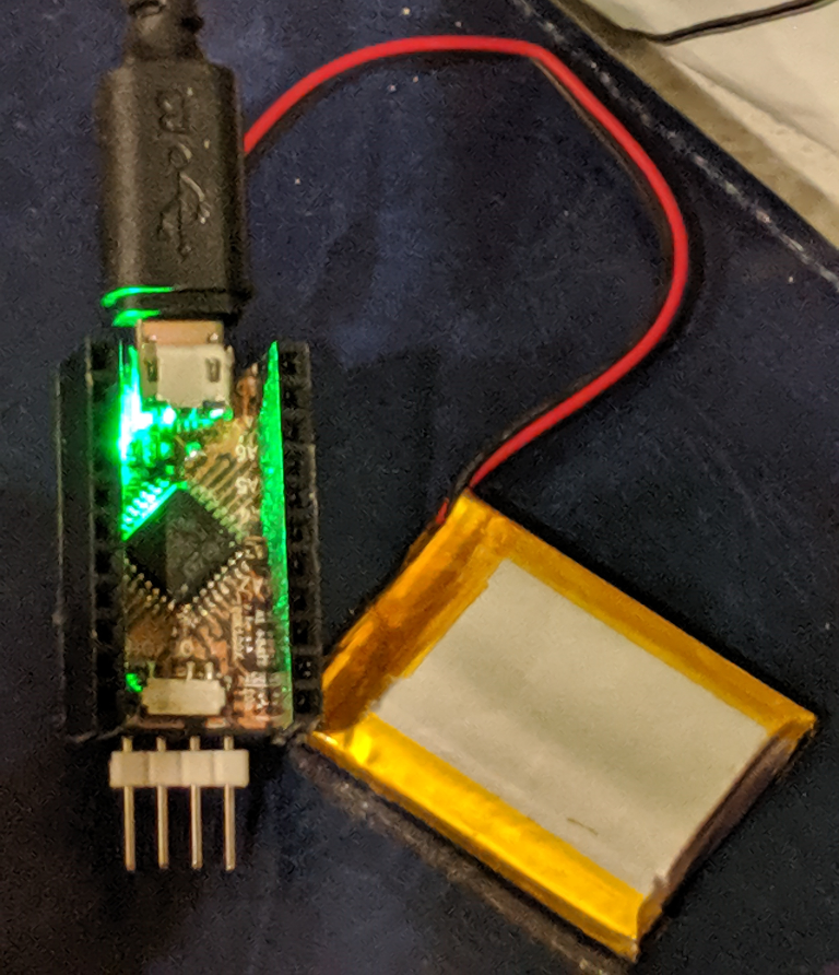
Hooray, it’s fully charged!
Step 1: Make a Battery-Powered Board
Our first step is designing an STM32 board with a battery charger, a battery connector, and an ADC connection to read the battery’s voltage. Most lithium batteries today have a charge voltage of 4.2V, which I like to think Douglas Adams would appreciate, but most STM32s have a maximum voltage of 3.6V. Just like when we run off of 5V supplies such as USB, we can use a 3.3V voltage regulator to make the STM32 happy, but we cannot use the ADC to read an analog voltage which is higher than the supply voltage.
I think that the easiest solution to that problem is to make a voltage divider with two resistors in series that have the same value. The junction where the resistors meet will have half of the voltage across the two of them put together, which would be a maximum of 2.1V – well within our 3.3V limit. Remember, if you have two resistors (R1 and R2) in series with a total voltage of V across them, the voltage across R1 is:
V1 = ( V * R1 ) / ( R1 + R2 )
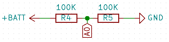
Simple voltage divider to cut the battery voltage in half for the ADC.
The downside to this approach is that the battery will also constantly discharge through the voltage divider, but if we use large resistor values we can keep the current low. I’ll use 100KOhm resistors in this example, which should only leak a maximum current of:
4.2 = I * 200,000
I = 21 microAmps
That’s significant if you’re using a coin cell battery, but not when you have 100s of milliAmp-hours. You might ask why we can’t use a much larger resistance to use even less current? You’ll find out when we start programming the ADC, but spoiler alert: less current means that you need a longer sampling time to get an accurate result. Even with these 100KOhm resistors, you will not get an accurate reading if you use the default ADC settings.
Next is the charging circuit. I’m going to use an MCP73831 because it is simple, widely-used, and easy to hand-solder in an SOT-25 package. Its maximum charge rate is only 500mA, but that’s fine for most applications. Here’s the datasheet; double-check the ‘typical application’ circuit against what you see here and what you design into your boards. Anyways, here’s the circuit that I use with it (you can find a full KiCAD project in this repository):
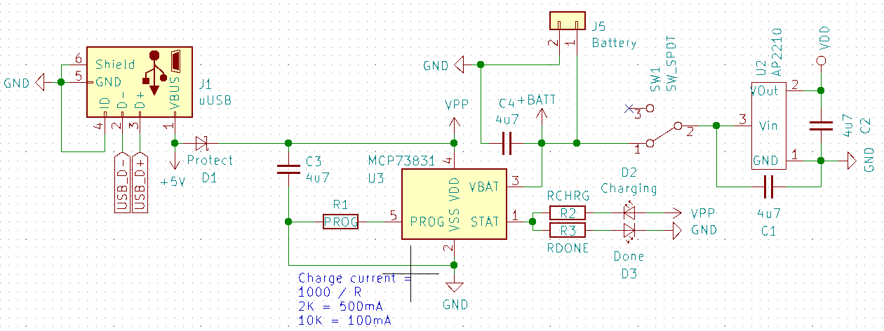
Battery-charging circuit using the MCP73831. Note that you should also add TVS diodes on the USB pins for any serious application, but I omitted them to save space on this example board.
The resistor connected to the PROG pin sets the charge current to 1000 / R Amps, if I’ve read the datasheet right. Usually I either use 2KOhm for 500mA, or 10KOhm for 100mA if I have a small battery. A good rule of thumb is to charge at a maximum of one Coulomb, and a quick shortcut for that is to estimate that you can charge an XmAh battery at XmA. So a lithium battery which is larger than about 500mAh should be fine with a 500mA charge current.
The STAT pin lets you check on the current charge status. You can connect it to a microcontroller, but it’s usually easiest to connect one or two LEDs so you can see when it finishes charging. In the circuit above, the LED on the top is lit when the STAT pin is held low, and the one on the bottom is lit when it is held high.
Besides that, there’s just the input/output capacitors and a schottky diode to protect against reverse polarity. The rest of the circuit is very similar to the STM32 board that I talked about in an earlier post about KiCAD:
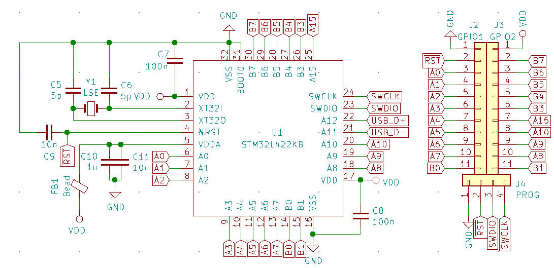
Simple STM32L422KB circuit. The crystal oscillator is optional, and I didn’t include a reset button. The ferrite bead and capacitors should help to filter noise on the analog voltage supply.
I used an STM32L422KB for this example because it has an easy-to-solder QFP32 package and a USB peripheral. It’s nice to have a microUSB port connected to the ‘voltage in’ line, because then you can use ordinary cables and USB ports to charge your gadget. And if you’re going to have a microUSB port, it had may as well work.
The board that I designed ended up working, but it was very difficult to hand-solder. I didn’t post an example project when I published this post, because my first revision wound up being very difficult to assemble. But I’ve uploaded a slightly less frustrating version to GitHub in the meantime. The board in the repository may not completely match the contents of this post, because I’m hoping to make improvements over time. But the core MCP73831 circuit and ADC voltage divider are not likely to change very much.
Anyways, on to the code!
Using the STM32 ADC
There are a few ‘gotchas’ to be aware of when using the ADC peripheral on an STM32, but it’s still pretty straightforward. It follows the usual basic format: “enable peripheral clocks”, “configure peripheral”, “enable peripheral”, “use peripheral”.
Besides the usual ‘enable clock’ bit, the ADC has a couple of bits set aside in the RCC->CCIPR register which say where its clock source should come from. By default, these bits are set to 0 which means ‘no clock source’, so the peripheral won’t work. It’s easiest to set them to 3 (0b11), which configures it to use the main system clock source:
RCC->AHB2ENR |=  ( RCC_AHB2ENR_ADCEN );
RCC->CCIPR   &= ~( RCC_CCIPR_ADCSEL );
RCC->CCIPR   |=  ( 3 << RCC_CCIPR_ADCSEL_Pos );
You’ll also need to set the GPIO pin that you want to use to Analog mode – I usually also clear all of the other GPIO registers associated with the pin. For example, to read ADC channel 6 from pin A1:
GPIOA->OTYPER       &= ~( 0x1 << 1 );
GPIOA->PUPDR        &= ~( 0x3 << ( 1 * 2 ) );
GPIOA->OSPEEDR      &= ~( 0x3 << ( 1 * 2 ) );
GPIOA->MODER        &= ~( 0x3 << ( 1 * 2 ) );
GPIOA->MODER        |=  ( 0x3 << ( 1 * 2 ) );
Although, you don’t really need to clear the MODER bits first, because there are only two of them per pin. Remember, the whole point of clearing bits before setting them is to avoid leaving ‘old’ bits set, and while 0b?? | 0b01 is not always 0b01, 0b?? | 0b11 is always 0b11. Anyways, our next step is to bring the ADC out of ‘deep sleep’ mode and enable a special internal voltage regulator. It takes 10-20 microseconds for the regulator to start up, so it’s a good idea to add a brief delay after turning the peripheral on. Or if you don’t want to delay, you could also write your program so that it turns on the ADC, performs some other startup logic which takes a bit of time, and then continues configuring the ADC. You can also calibrate the ADC at this point if you want to – it’s as easy as setting the ADCAL bit in ADC->CR, then waiting for it to be un-set by the chip:
// Simple way to do a busy-loop delay with GCC.
void __attribute__( ( optimize( "O0" ) ) ) delay_cycles( uint32_t cyc ) {
  for ( uint32_t d_i = 0; d_i < cyc; ++d_i ) { asm( "NOP" ); }
}

int main( void ) {
  // ( ... )
  // Bring the ADC out of 'deep power-down' mode.
  ADC1->CR    &= ~( ADC_CR_DEEPPWD );
  // Enable the ADC voltage regulator.
  ADC1->CR    |=  ( ADC_CR_ADVREGEN );
  // Delay for a handful of microseconds.
  delay_cycles( 100 );
  // Calibrate the ADC if necessary.
  if ( perform_calibration ) {
    ADC1->CR  |=  ( ADC_CR_ADCAL );
    while ( ADC1->CR & ADC_CR_ADCAL ) {};
  }
  // ( ... )
}
It would be better to use the SysTick peripheral or a timer to generate the delay, but I’ll leave that as an exercise to the reader 🙂
The last thing we need to do before turning the ADC on is to configure its ‘sequence’. If you want to read multiple ADC channels, you can tell the peripheral to read them one-by-one in a sequence instead of re-configuring the ADC every time you want to read a different channel. But for this simple example, we’ll just configure a single conversion:
// First, set the number of channels to read during each sequence.
// (# of channels = L + 1, so set L to 0)
ADC1->SQR1  &= ~( ADC_SQR1_L );
// Configure the first (and only) step in the sequence to read channel 6.
ADC1->SQR1  &= ~( 0x1F << 6 );
ADC1->SQR1  |=  ( 6 << 6 );
// Configure the sampling time to 640.5 cycles.
ADC1->SMPR1 &= ~( 0x7 << ( 6 * 3 ) );
ADC1->SMPR1 |=  ( 0x7 << ( 6 * 3 ) );
There are multiple SQR and SMPR registers containing the configuration bits for different sequence numbers and channels. The SQRx registers let you set how many channels to read, and in what order. The SMPRx registers let you set the sampling time for each channel. For more information about these registers, check out the ADC peripheral’s chapter in the reference manual. In our case, we only read one channel, and we set it to use a long sampling time because of how little current can flow through the branch that the ADC is reading from.
Now, when you want to check the battery voltage in your code, all you have to do is set the ADSTART bit in ADC->CR and read ADC->DR once the EOC (End Of Conversion) bit is set in ADC->ISR. It’s also a good idea to set the EOS (End Of Sequence) bit in ADC->ISR to get the ADC ready to perform another conversion later on, and this sort of logic had may as well go in a separate function:
// Perform a single ADC conversion.
// (Assumes that there is only one channel per sequence)
uint16_t adc_single_conversion( ADC_TypeDef* ADCx ) {
  // Start the ADC conversion.
  ADCx->CR  |=  ( ADC_CR_ADSTART );
  // Wait for the 'End Of Conversion' flag.
  while ( !( ADCx->ISR & ADC_ISR_EOC ) ) {};
  // Read the converted value (this also clears the EOC flag).
  uint16_t adc_val = ADCx->DR;
  // Wait for the 'End Of Sequence' flag and clear it.
  while ( !( ADCx->ISR & ADC_ISR_EOS ) ) {};
  ADCx->ISR |=  ( ADC_ISR_EOS );
  // Return the ADC value.
  return adc_val;
}
The returned value is on a scale of 0 – 4095, because it is a 12-bit ADC. A value of zero means that the ADC reads zero volts, and a value of 4095 means that the ADC reads the supply voltage, which is 3.3V in this case. Since the voltage divider cuts the battery’s voltage in half, we can calculate the total voltage with this equation:
VBatt = ( ADC_value * 2 / 4095 ) * 3.3
And sure enough, when the MCP73831 finishes charging the battery, I get readings of about 2600, which comes out to 4.18V.
With lithium-ion batteries, somewhere around 3-3.3V is probably ‘low’, but it depends on the battery and how you use it. The more current you draw, the more the voltage will ‘droop’ below its ‘real’ value, so a reading of something like 2.8V could be safe in some situations and dangerous in others. And we actually have another accuracy problem here – if the battery drops below about 3.55V, the voltage regulator (which drops <=0.25V in this case) won’t be able to provide a stable 3.3V output, and the supply voltage will drop. That will cause our battery monitor to think that the battery is more charged than it really is, because the actual maximum ADC reading will be lower than 3.3V, and the microcontroller has no way to know that. In this case, I’m okay with just saying that a reading of 3.3V means that the battery is ‘low’, even if there might still be a decent amount of life left in the battery at that point; better safe than sorry. But the AP2210 voltage regulator is also available in 3V and 2.5V variants, and these chips can run off of as little as 1.8V – food for thought.
Conclusions
So that’s a very quick and basic primer on how to integrate a lithium-ion battery into your STM32-based projects, and a few of the challenges that emerge from this super-simple approach. You should be able to use the same code to read any sort of analog voltage, and if the signal that you’re reading isn’t being fed through a large-value resistor, you can probably use a much shorter ADC sampling time.
Unfortunately, my first revision of this board turned out to be a pain to assemble. But here is the link to a GitHub repository with a slightly less-frustrating version of the board. I haven’t quite finished polishing an example firmware image which reads the battery voltage and periodically prints it over UART, but that should be coming soon and I’m hoping to write a simple introduction to UART communication to go with it 🙂


Ralph Doncaster
March 17, 2020 at 8:45 am
You can use larger resistors (i.e. 1M) in the divider and still use short sampling times if you add a small capacitor (1n-100n).
Vivonomicon
April 14, 2020 at 11:45 am
Interesting, thank you for the suggestion! I guess it makes sense that a capacitor could act as a buffer that ‘charges up’ between reads, I’ll have to try that.
BOGDAN-MIHAI NISTOR
May 29, 2020 at 7:33 am
This was a great article and it helps me a lot with the understanding of my project!
I have actually used a 1nF capacitor and 2 resistances of 1.2M and 3M. I wanted to ask you, how would the capacitor affect the formula calculating the battery voltage? (if it even affects it at all)
Thank you,
Bogdan
Vivonomicon
June 6, 2020 at 11:48 am
Well I’m not the original commenter, but I don’t think the capacitor should affect the math formula.
If I understand the suggestion correctly, you would connect the capacitor to the ADC input pin and ground. It would ‘charge up’ between readings and deliver current to the peripheral more quickly than if the charge carriers needed to flow through the high-resistance ‘top half’ of the voltage divider.
fadi
May 16, 2020 at 12:13 pm
I am working on an arduino stm how can i properly control analog settings
Vivonomicon
June 6, 2020 at 12:03 pm
The Arduino IDE should include a library for interacting with the ADC – I think the simplest way might be with the ‘analogRead()’ method? You might be able to find some support on their Github repository, like:
https://github.com/stm32duino/Arduino_Core_STM32/issues/552