
As you start to re-use components like sensors and displays, you might start to get frustrated with how long it takes to set up new projects. Copying and cleaning code between old working examples and new ideas can be time-consuming and tedious. It’s much easier to simply copy a few portable library files around. While there are plenty of existing libraries for these sorts of peripherals and external devices, it’s good to learn how to write your own, and this is also a good way to demonstrate a few ‘gotchas’ that you should be aware of when using C++ in an embedded application.
In this tutorial, we will walk through setting up a couple of object-oriented classes to represent a common communication ‘I/O’ peripheral model:
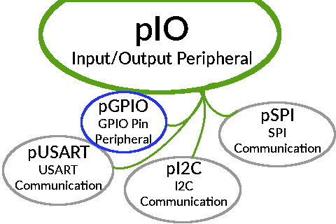
One example of what a simple common communication model could look like.
For simplicity’s sake, I’ll only cover a class for a bank of GPIO pins to demonstrate the core requirements for using C++ in an embedded application, but you can also find similar classes for the I2C peripheral and an SSD1306 OLED display in the example Github repository’s reference implementation of the concepts presented in this tutorial.
Writing a Base IO Class
Since this post’s main subject is embedded C++ inheritance, let’s start by writing a basic ‘Input/Output’ class which declares a few methods common to most communication peripherals. It will have a ‘status’ value to record what state the peripheral is in, virtual methods for single read/write operations, and some common ‘enable/disable/reset’ commands:
// Global macro definitions.
#define pSTATUS_ERR (0)
#define pSTATUS_SET (1)
#define pSTATUS_ON  (2)

class pIO {
public:
  pIO();
  // Common read/write methods.
  virtual unsigned read(void);
  virtual void     write(unsigned dat);
  // Common peripheral control methods.
  virtual void     clock_en(void);
  virtual void     reset(void);
  virtual void     disable(void);
  // Getters/Setters.
  virtual int      get_status(void);
protected:
  // Expected peripheral status.
  int status = pSTATUS_ERR;
  // Enable/disable/reset register definitions.
  __IO uint32_t *enable_reg = 0;
  __IO uint32_t *reset_reg  = 0;
  uint32_t       enable_bit = 0;
  uint32_t       reset_bit  = 0;
private:
};
The ‘enable’ and ‘reset’ register and bit variables keep track of which values to modify to turn the peripheral on or off, and to reset it. The __IO qualifier is a macro defined in the CMSIS device header files, and here it translates to volatile.
For simplicity’s sake, you can see in the Github repository’s Makefile that I disabled C++ exceptions and RTTI in this example by passing the -fno-exceptions and -fno-rtti flags to arm-none-eabi-g++. That lets us avoid pulling in more libraries for now, but it also means that we can’t have pure virtual methods. So the source file will need to have some default definitions for all of the virtual methods declared in the header file:
#include "core.h"

// (Empty default constructor.)
pIO::pIO() {}

// Read the peripheral's default data length. (Up to a word)
unsigned pIO::read(void) { return 0; }

// Write the peripheral's default data width (up to a word)
void pIO::write(unsigned dat) {}

// Enable the peripheral clock.
void pIO::clock_en(void) {
  if (status == pSTATUS_ERR) { return; }
  *enable_reg |= enable_bit;
  status = pSTATUS_ON;
}

// Reset the peripheral.
void pIO::reset(void) {
  if (status == pSTATUS_ERR) { return; }
  *reset_reg |= reset_bit;
  *reset_reg &= ~(reset_bit);
}

// Turn the peripheral off.
void pIO::disable(void) {
  if (status == pSTATUS_ERR) { return; }
  *enable_reg &= ~(enable_bit);
  status = pSTATUS_SET;
}

// Return the current peripheral status,
// as far as the library knows.
int pIO::get_status(void) { return status; }
The read and write methods don’t do anything by default, but the enable/disable/reset ones have a fairly predictable behavior of setting/resetting bits in a register.
Writing a Derived Class
This general I/O structure is more reasonable for communication peripherals like I2C, SPI, or USART, but we can also finagle a GPIO bank into it:
class pGPIO : public pIO {
public:
  // Constructors.
  pGPIO();
  pGPIO(GPIO_TypeDef* bank);
  // Common r/w methods from the core I/O class.
  unsigned read(void);
  void     write(unsigned dat);
  // GPIO-specific methods.
  // Register modification methods; platform-specific.
  #if   defined(STM32F0) || defined(STM32F3) || defined(STM32L0)
    void   set_pin_mode(unsigned pin_num, unsigned mode);
    void   set_pin_type(unsigned pin_num, unsigned otype);
    void   set_pin_speed(unsigned pin_num, unsigned ospeed);
    void   set_pin_pupd(unsigned pin_num, unsigned pupd);
    void   set_pin_af(unsigned pin_num, unsigned af);
  #elif STM32F1
    void   set_pin_cfg(unsigned pin_num, unsigned cfg);
  #endif
protected:
  // Reference GPIO register struct.
  GPIO_TypeDef* gpio        = NULL;
private:
};
The STM32F1 line of chip is one of ST’s older ARM lines, and it uses a different way of configuring GPIO pins than what was covered in most of my previous tutorials; it has four bits for each pin spanning two ‘configuration’ registers. Two bits set the pin’s mode, and two bits select different configurations of that mode. You can check the STM32F1 reference manual for more details (Section 9.2).
The constructor sets the status to ‘set’ after defining the ‘enable’ and ‘reset’ registers and bits declared in the base pIO class, but I won’t copy the long string of ‘if / else if / else if / …’ statements to determine the right bit for a given GPIO bank here. You can see the basic idea in the reference Github repository’s pGPIO implementation.
The read and write methods can simply return and set the IDR and ODR (‘Input Data Register’ / ‘Output Data Register’) values in the given GPIO bank:
/*
 * Read the entire 16 bits/pins in the GPIO bank.
 */
unsigned pGPIO::read(void) {
  if (status == pSTATUS_ERR) { return 0; }
  // Return the current value of all 16 pins.
  return gpio->IDR;
}

/*
 * Write all 16 bits/pins in the GPIO bank.
 * This will set all 16 pins to the provided value, 0s included.
 */
void pGPIO::write(unsigned dat) {
  if (status == pSTATUS_ERR) { return; }
  // Write to all pins at once.
  gpio->ODR = dat & 0xFFFF;
}
The status checks are optional, but they should prevent an uninitialized object from trying to access memory locations relative to a null pointer if, for example, the gpio pointer is still set to NULL in the methods above. And the register-setting methods are just small wrappers for writing their corresponding register values. For example, the STM32F1 line’s single GPIO pin configuration method looks like:
void pGPIO::set_pin_cfg(unsigned pin_num, unsigned cfg) {
  if (status == pSTATUS_ERR) { return; }
  if (pin_num < 8) {
    gpio->CRL &= ~(0xF << (pin_num * 4));
    gpio->CRL |=  (cfg << (pin_num * 4));
  }
  else {
    gpio->CRH &= ~(0xF << ((pin_num - 8) * 4));
    gpio->CRH |=  (cfg << ((pin_num - 8) * 4));
  }
}
Using the Classes
You can write a separate class for individual GPIO pins and add convenience ‘toggle pin’ methods like I did in the reference Github project, but if you’re in a hurry you can also use the pGPIO class methods described above to set a pin to push-pull output mode and toggle it between on/off. For example, with an STM32F103 board you could do something like this:
// (#includes...)

// Static values/macros.
const int led_delay = 500;
pGPIO led_gpio;
#define LED_BANK (GPIOB)
#define LED_PIN  (12)

// FreeRTOS task to toggle an LED.
static void led_task(void *args) {
  int delay_ms = *(int*)args;
  unsigned led_bank_state = 0;

  while (1) {
    // Read the current GPIO state.
    led_bank_state = led_gpio.read();
    // Write the same value, XOR'd with the LED pin.
    led_gpio.write(led_bank_state ^ (1 << LED_PIN));
    // Wait a bit.
    vTaskDelay(pdMS_TO_TICKS(delay_ms));
  }
}

// Main method.
int main(void) {
  // (startup code...)

  // Initialize the LED pin's GPIO bank.
  led_gpio = pGPIO(LED_BANK);
  led_gpio.clock_en();
  // Initialize the LED pin.
  led_gpio.set_pin_cfg(LED_PIN, 0x02);

  // Create a blinking LED task for the on-board LED.
  xTaskCreate(led_task, "Blink_LED", 128, (void*)&led_delay,
              configMAX_PRIORITIES-7, NULL);
  // Start the scheduler.
  vTaskStartScheduler();
  // This should never be reached; the FreeRTOS scheduler should
  // be in charge of the program's execution after starting.
  while (1) {}
  return 0;
}
This looks like it should work, but if you build and flash it, your board’s LED probably won’t start blinking. If you check in a debugger, you might see your program crashing or constantly resetting when it tries to call methods from the base class. What gives? For a hint, we can step through the program until the pGPIO struct has been created, and check what it looks like:
(gdb) p led_gpio
$2 = {<pIO> = {_vptr.pIO = 0x0, status = 1, enable_reg = 0x40021018, reset_reg = 0x4002100c,
  enable_bit = 8, reset_bit = 8}, gpio = 0x40010c00}
Extra Memory Sections for C++
Those registers and bits all look correct for an STM32F103, except for the first _vptr.pIO value – it’s set to zero, a null pointer. The object’s base class has not been constructed, so when our program tries to call one of its methods, it winds up calling a memory location somewhere near the very beginning of memory, which probably lands it in the vector table for a small class. In my case, the first virtual method I called landed on the reset handler and caused the chip to jump back to the program’s starting point whenever it reached the part that was supposed to initialize a peripheral.
To avoid this, we need to add a few more memory sections to our linker script’s SECTIONS block, which are specific to C++. These areas of memory hold pointers to constructors and destructors that the compiler expects to be called before and after the main program is run. The preinit_array and init_array sections hold functions which should be called before the program, and the fini_array section holds functions which should be called after. In an embedded device, there is no real ‘after’, but we can still include the memory section for completeness:
.preinit_array :
{
  . = ALIGN(4);
  _spreinit_array = .;
  KEEP (*(.preinit_array))
  KEEP (*(.preinit_array*))
  _epreinit_array = .;
  . = ALIGN(4);
} >FLASH
.init_array :
{
  . = ALIGN(4);
  _sinit_array = .;
  KEEP (*(.init_array))
  KEEP (*(.init_array*))
  _einit_array = .;
  . = ALIGN(4);
} >FLASH
.fini_array :
{
  . = ALIGN(4);
  _sfini_array = .;
  KEEP (*(.fini_array))
  KEEP (*(.fini_array*))
  _efini_array = .;
  . = ALIGN(4);
} >FLASH
Once those sections are included in the program’s memory, we need to call the functions they point to at the very beginning of our main method:
extern void (*_spreinit_array []) (void) __attribute__((weak));
extern void (*_epreinit_array [])(void) __attribute__((weak));
extern void (*_sinit_array [])(void) __attribute__((weak));
extern void (*_einit_array [])(void) __attribute__((weak));

int main(void) {
  // Call C++ static initializers.
  // ('preinit_array' functions are unlikely if the user
  //  doesn't define any, I think. But check for them anyways.)
  int cpp_count = 0;
  int cpp_size = &(_epreinit_array[0]) - &(_spreinit_array[0]);
  for (cpp_count = 0; cpp_count < cpp_size; ++cpp_count) {
    _spreinit_array[cpp_count]();
  }
  // ('init_array' sections call static constructors)
  cpp_size = &(_einit_array[0]) - &(_sinit_array[0]);
  for (cpp_count = 0; cpp_count < cpp_size; ++cpp_count) {
    _sinit_array[cpp_count]();
  }

  // (main program)
  // ...
}
Unlike the .data and .bss sections in RAM which our startup code populates, these sections hold pointers to functions. So instead of copying each element from one place to another, we call each element once. With that done, the led_gpio object should get created successfully when the program is run:
(gdb) p led_gpio
$2 = {<pIO> = {_vptr.pIO = 0x8001be0 <vtable for pGPIO+8>, status = 1, enable_reg = 0x40021018, reset_reg = 0x4002100c, enable_bit = 8,
    reset_bit = 8}, gpio = 0x40010c00}
That looks better; 0x08001be0 is a few kilobytes into the chip’s flash memory, so it looks like the base class probably exists now. And sure enough, the LED should start blinking when the program is run.
Conclusions
While there’s not much of a reason to use inheritance for blinking an LED, it is a useful concept for organizing more complex applications, even in an embedded context. Most of Adafruit’s Arduino libraries are written as C++ classes, and I like the idea of having distinct objects for both peripherals within the chip and external devices that the chip can communicate with.
It seems like a natural way to think about things; each important part in your design can have its own class in your application, and similar parts can share functionality. For example, there are a wide variety of displays ranging from OLEDs to TFTs to E-Ink which use nearly identical “4-Wire SPI” communication standards; those could all be derived from a base ‘display’ class which held common methods like ‘write command byte’, ‘write data byte’, ‘draw framebuffer’, etc.


Maxim
December 12, 2019 at 12:17 am
> but it also means that we can’t have pure virtual methods
Well, you’re not exactly right. You can’t get same behavior like glibc one, that’s for sure. When you call pure virtual method it calls in fact __cxa_pure_virtual method (e.g. http://infocenter.arm.com/help/index.jsp?topic=/com.arm.doc.dui0491i/Bdifadee.html). So you may implement this by yourself by throwing some error in debug output and hang MCU after that.
Vivonomicon
February 11, 2020 at 3:51 pm
Oh, thanks for the correction – I am sort of learning about C++-specific memory sections as I go.
JohnC
January 6, 2020 at 3:24 am
In your experience, does C++ use much memory, also is it worth going full OOP for a small/medium-sized embedded project?
Vivonomicon
February 11, 2020 at 3:24 pm
In my experience, C++ doesn’t use much more memory if you don’t use its more complicated features. It’s nice to be able to use polymorphism, but I haven’t actually worked on an embedded C++ project which was large enough to justify it.
I think that C is fine for most simple applications, although you’ll probably end up re-using a lot of driver code if you decide to write your own. I keep wanting to write some sort of big universal HAL which could take advantage of simple C++ features like virtual functions, but it’d be a lot of work.
Lukas G
April 27, 2020 at 5:42 am
Hi,
first of all thank you so much for this article. It was very helpful and for now I will use the sample principle that you showed here for writing all my drivers.
Just wanted to mention, that there is a way to just call “__libc_init_array” in the startup code instead of the manual call for static initializers. Newlib contains this function to do exact the same thing as the code at the beginning of your main function. Of course you need to link with “–specs=nano.specs” or “–specs=nosys.specs” if you don’t want to use nano.
The source in newlib can be found here (it’s a relatively up-to-date mirror of the original codebase.
https://github.com/bminor/newlib/blob/master/newlib/libc/misc/init.c
Cheers and keep up the awesome work!
Lukas
Vivonomicon
June 6, 2020 at 12:51 pm
Oh, interesting – thank you for the tip!
The code in this post was sort of patched together from a bunch of searching through GCC documentation and trying things to see what worked, so it makes sense that there are easier ways to handle the common initialization stuff. Thanks for pointing that out.