When you want to pick a microcontroller for a project, it can be useful to have a bunch of quick references to find the smallest/cheapest one that will fit the parts you want to use. Usually the information is freely available in datasheets, but those are usually PDF files with pinout/peripheral information spanning several pages.
So I’ve been playing with ways to partially automate the process of generating some nice reference images. I’m not exactly happy with what I have yet, but it’s not the sort of thing that merits spending a ton of time on, and I think I scripted away enough of the tedium that it isn’t too frustrating to make these sorts of tables. You wind up with reference images like this:
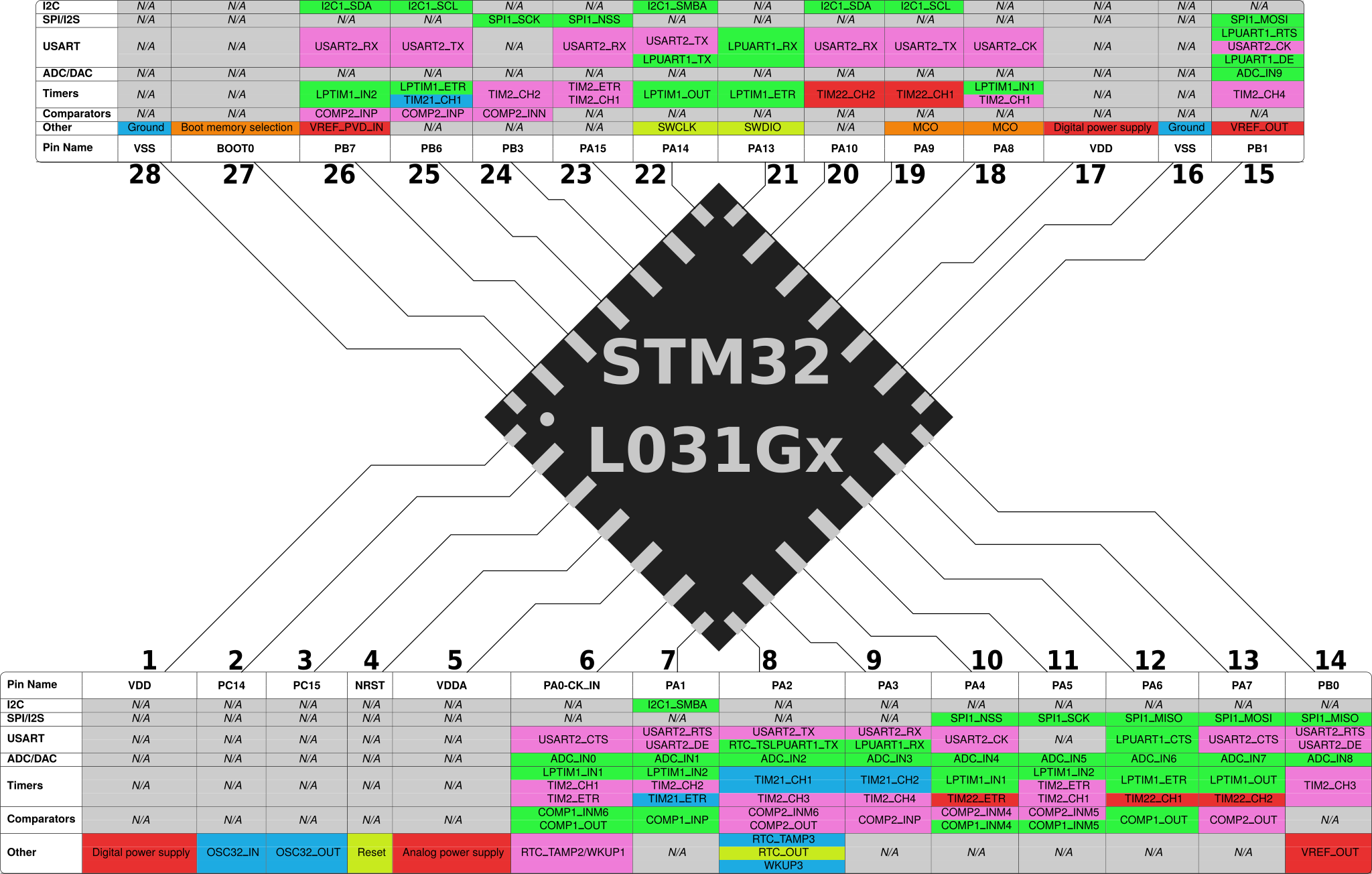
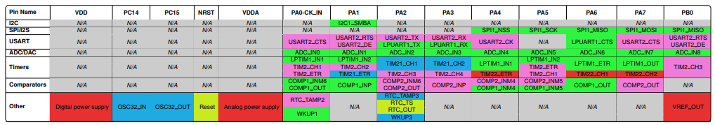
STM32L031Gx Pinout / Peripherals
Honestly, this post would be sort of moot if I could find nice CSV files or spreadsheets of STM32 pinouts and peripherals (see below). Maybe other vendors distribute information in that format, but I couldn’t find many for ST’s chips. And that means that I ended up with a sort of convoluted process.
A fragile Python script runs the pdftotext utility to convert an STM32 datasheet into a pinout table containing peripheral information. The automatic formatting doesn’t include table cell boundaries, so I couldn’t figure out how to put all of the peripherals associated with a pin on the same line quickly; someone needs to manually perform that step before running a second Python script which generates LaTeX files representing formatted peripheral tables. The PDF files generated by pdflatex can then be imported into Inkscape, where the table columns can be connected to the pins on an image of the chip’s outline. So, let’s get started!
Note: I ended up finding a better way to parse STM32 datasheets using a project called Tabula – see this newer post for more information. My first attempt presented in this post ended up working pretty poorly, but that’s life for you. Sometimes it takes a few tries to find a good solution.
Step 1: Parse the datasheet.
The closest thing I could find to a table mapping each pin on an STM32 chip was the table presented in their datasheets. Here’s a link to the datasheet for the chip corresponding to the image at the top of this post. As of the time of writing, the pin definitions can be found in Table 15 (“Pin definitions”), under Section 4 (“Pin descriptions”). ST has been adopting a more modern style in some of their newer documents, but hopefully they’ll keep the datasheet styling the same for awhile.
I wrote a quick Python script to run pdftotext with some formatting options, and parse the output into a semi-finished table; you can find it in this GitHub repository. The syntax is very simple: python3 pin_extract.py datasheet.pdf. The script takes the formatted output from pdftotext and formats it into a CSV-style table using ‘#’ characters as delimiters. But unfortunately, pdftotext intersperses peripheral definitions on different rows from the actual pin names in a way that is difficult to automatically parse:
...
PH1-
-#-#-#-#-#-#6#6#I/O#TC#-#-#-
OSC_OUT
4#D5#4#4#4#4#7#7#NRST#I/O#-#-#-#-
LPTIM1_IN1,
-#-#-#-#-#-#1#1#PC0#I/O#FT#-#EVENTOUT,#-
LPUART1_RX
-#E1#-#-#-#"0"#8#8#VSSA#S#-#-#-#-
5#C4#5#5#5#5#9#9#VDDA#S#-#-#-#-
LPTIM1_IN1,
TIM2_CH1,#COMP1_INM6,
6#E5#6#6#6#6#-#-#PA0-CK_IN#I/O#TC#-#USART2_CTS,#ADC_IN0,
TIM2_ETR,#RTC_TAMP2/WKUP1
COMP1_OUT
...
I couldn’t find a better/easier way to pull tables out of PDF files offline, but suggestions are certainly welcome. You could probably figure this out by having special rules for power supply pins and common cases which span multiple lines like the oscillator and RTC pins, then looking for peripheral lines which don’t end in a comma. But it would be tricky, because there are two separate columns holding potential peripheral mappings and not every pin has an entry in both of them.
Step 2: Clean up the auto-generated output.
In lieu of a good automatic solution, I decided to take a few (okay, several) minutes per datasheet to manually collect the stray peripheral definitions into one column per pin row. It’s not perfect, but it’s also not too bad; the end of a peripheral cell is usually marked by the lack of a trailing comma. Anyways, I try to end up with something like this:
...
-#-#-#-#-#-#6#6#PH1#I/O#TC#-#OSC_OUT
4#D5#4#4#4#4#7#7#NRST#I/O#-#-#Reset
-#-#-#-#-#-#1#1#PC0#I/O#FT#-#EVENTOUT,LPTIM1_IN1,LPUART1_RX
-#E1#-#-#-#"0"#8#8#VSSA#S#-#-#Analog ground
5#C4#5#5#5#5#9#9#VDDA#S#-#-#Analog power supply
6#E5#6#6#6#6#-#-#PA0-CK_IN#I/O#TC#-#USART2_CTS,ADC_IN0,LPTIM1_IN1,TIM2_CH1,COMP1_INM6,TIM2_ETR,RTC_TAMP2,WKUP1,COMP1_OUT
...
The first script briefly describes this format when it finishes running, but who am I kidding? These scripts are too hack-y to be user-friendly, and I’m sorry about that. But once you have the file in the correct format, you can run: python3 pin_ingest.py mid_datasheet.txt [pin_column]. Most STM32 datasheets provide pinouts for several very similar packages – pick the ‘pin_column’ ID which corresponds to the one that you want to generate tables for, starting from zero for the left-most one.
This second script parses the formatted output into a LaTeX file with the chip’s pin:peripheral mappings sorted into a format that I hope is easier to read – you can run pdflatex file.tex to convert .tex files into PDFs. If you get errors about missing modules, you may need to install the full “texlive” packages:
Example LaTeX table render
The colors are based on a peripheral’s number – 1 is green, 2 is pink, 3 is blue, 4 is red, 5 is yellow, 6 is orange, and then it wraps around. Some special cases like power, reset, and oscillator pins also get colors, to avoid having the ‘Other’ row be all grey.
That PNG image is pretty low-resolution, but Inkscape can import the actual PDF file as a vector object. The script generates two tables, each with half of the pins available on the package; you get a better aspect ratio if you put a stylized image of the chip between two tables, instead of putting it above one very wide table.
Step 3: Format SVG file
Once you have PDF tables of the chip’s pin:peripheral mappings, you can turn them into SVGs by importing them into Inkscape. Simply open the PDF file, and Inkscape will ask you how you want to import it. De-select the “embed images” and “[font]” options, then hit ‘Ok’. I don’t think the detail slider makes much difference for a text table.
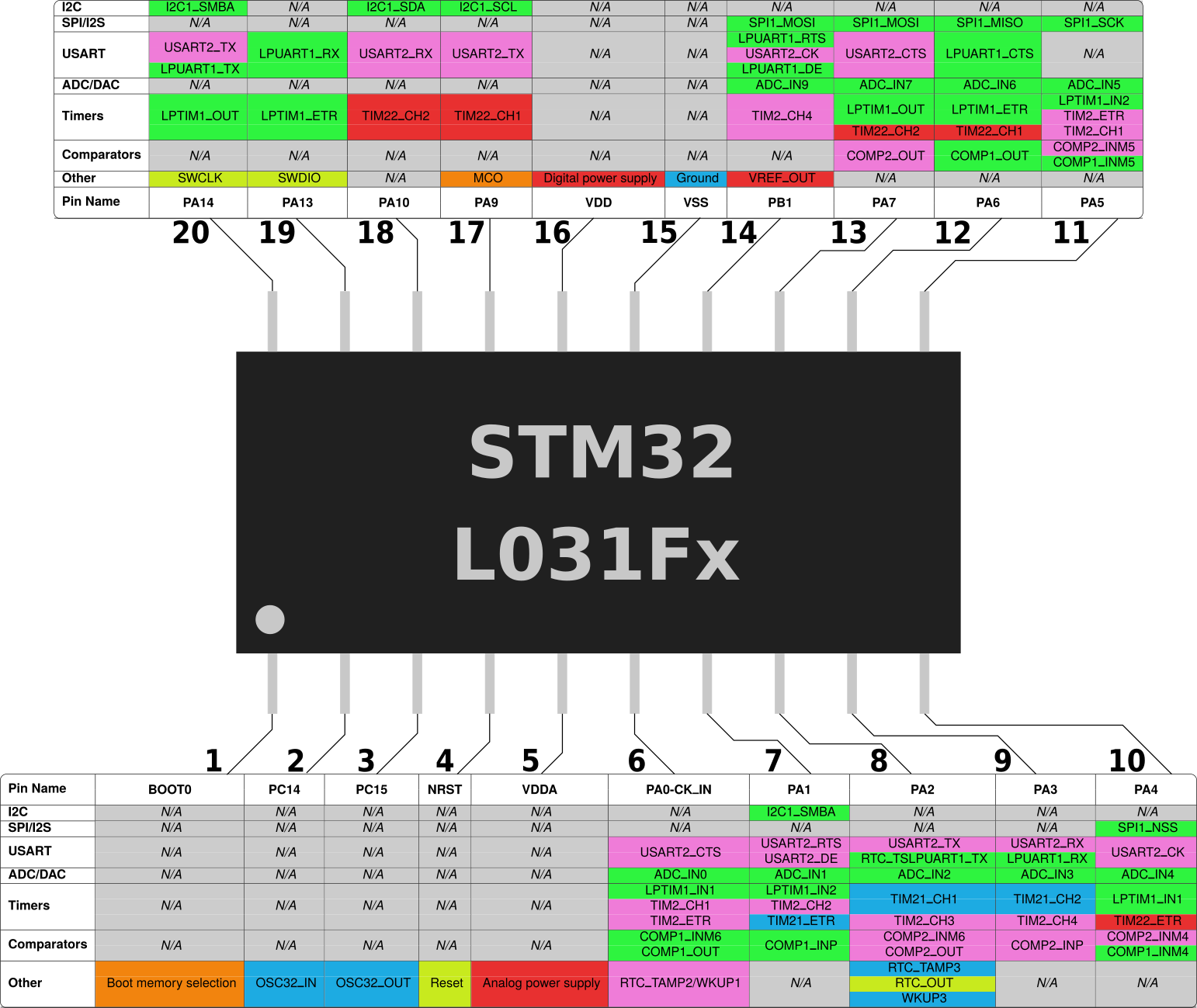
Once you import both tables, you can copy them into a document containing an outline of the chip package. I made the QFN28 image shown here by overlaying silver rectangles over a black square, grouping them, and then rotating the group by 45 degrees. You may also need to set your document’s background color to white if you export it in a format that supports transparency, such as PNG:
Blank pin map, without lines or labels
Once you’re happy with how the tables are aligned, it just takes another few minutes to draw lines from each ‘pin’ on the package to the corresponding table column. You can hold the ‘ctrl’ key while using the pen tool in Inkscape to snap your lines to 15-degree increments. Then I usually add a ‘title’ on top of the chip package, and a bit of large text to mark the pin number for each table column:
STM32L031Gx Pinout / Peripherals – can you spot the difference?
Conclusions
So, that’s a first attempt at making almost-automatic STM32 peripheral pinout images. I didn’t go into much detail on the Python scripts, because they aren’t very interesting or well-written. They mostly just run shell commands and parse files, and they don’t do much error checking. I might get around to fixing that if I end up making a lot of these, but there are only so many hours in a day. You can find them in this GitHub repository, and I’m sorry that they aren’t in better shape.
Also note that there is an error-prone manual step in this process, so let me know if you see any discrepancies with the datasheets. I’m also sure that trying other datasheets will turn up plenty of other bugs in the scripts, and the scripts won’t work with grid-based pinouts like BGA/WLCSP packages because they’ll try to cast the alphanumeric pin names into integers. I can’t really spend much time patching corner cases in this skeletal logic, but it was a fun chance to try a little bit of design. I don’t get many opportunities to try to make things that look nice, in case you couldn’t tell.
Anyways, here are a few other PNGs that I made in the same way. With any luck, it won’t take much longer to make a bunch more, including QFP packages and more complex chips with more peripherals:
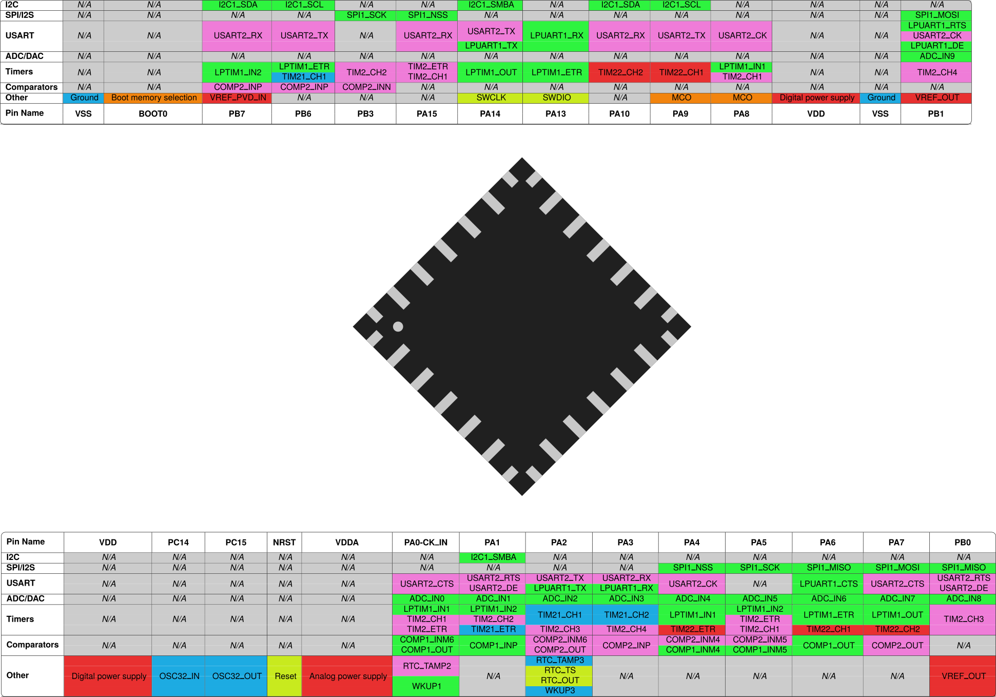
STM32L031Fx pinout
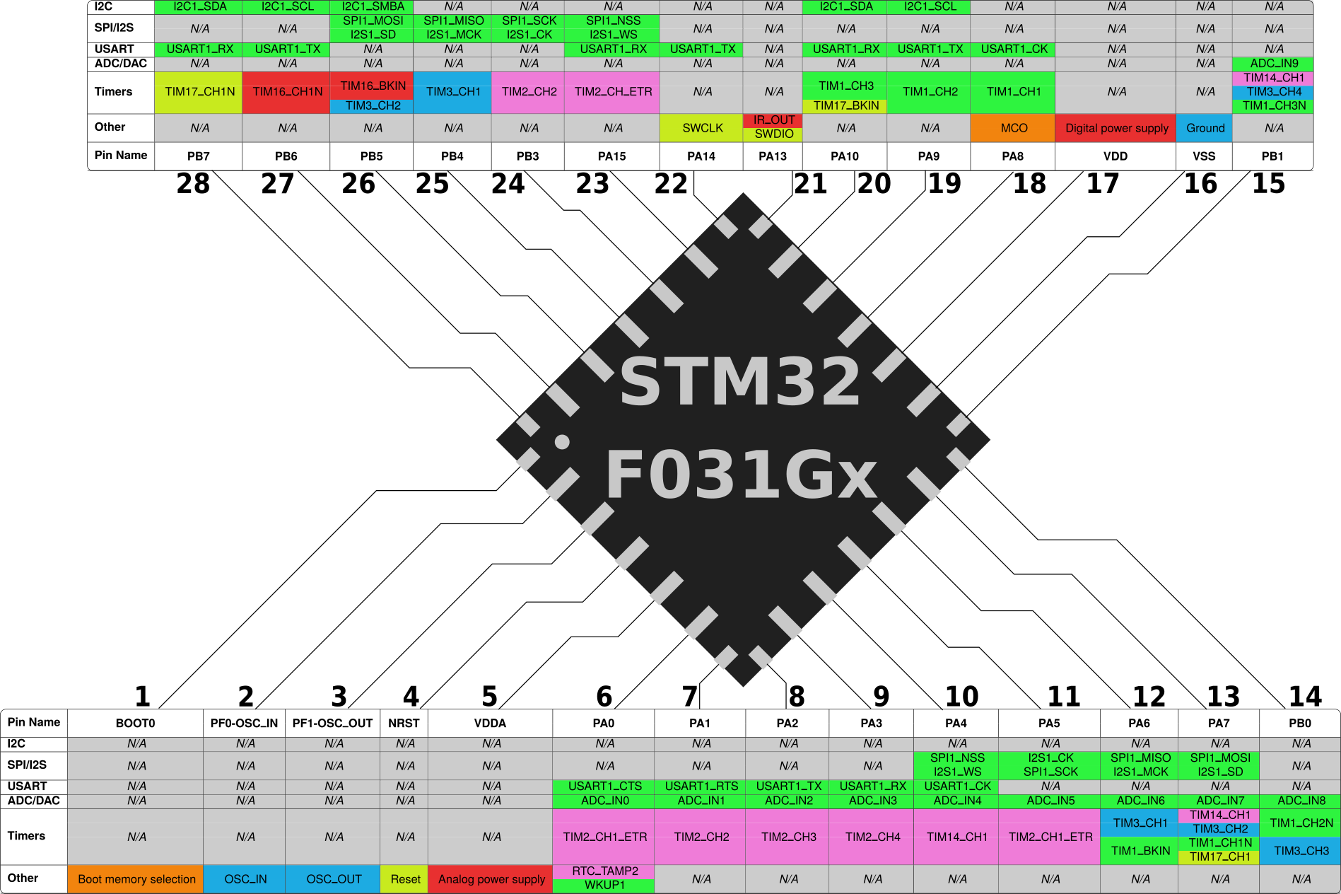
STM32F031Gx pinout
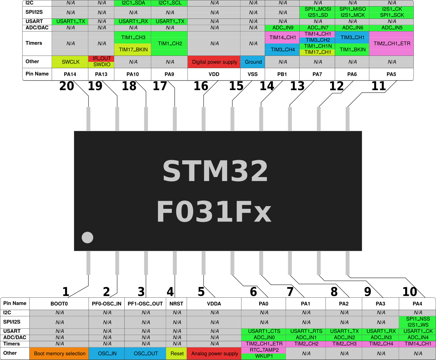
STM32F031Fx pinout