
Whenever I talk to someone about FPGAs, the conversation seems to follow a familiar routine. It is almost a catechism to say that ‘FPGAs are very interesting niche products that, sadly, rarely make sense in real-world applications’. I often hear that organizations with Money can afford to develop ASICs, while hobbyists are usually better served by today’s affordable and powerful microcontrollers except in some very specific circumstances like emulating old CPU architectures. I don’t have enough experience to know how accurate this is, but I do have a couple of projects that seem like they could benefit from an FPGA, so I decided to bite the bullet and learn the basics of how to use one.
I chose a popular $25 development board called the ‘Icestick‘ to start with. It uses one of Lattice’s iCE40 chips, which is nice because there is an open-source toolchain called Icestorm available for building Verilog or VHDL code into an iCE40 bitstream. Most FPGA vendors (including Lattice) don’t provide a toolchain that you can build from source, but thanks to the hard work of Clifford Wolf and the other Icestorm contributors, I can’t use “maddeningly proprietary tools” as a reason not to learn about this anymore.
One thing that FPGAs can do much better than microcontrollers is running a lot of similar state machines in parallel. I’d eventually like to make a ‘video wall’ project using individually-addressable LEDs, but the common ‘Neopixel’ variants share a maximum data rate of about 800kbps. That’s probably too slow to send video to a display one pixel at a time, but it might be fast enough to send a few hundred ‘blocks’ of pixel data in parallel. As a small step towards that goal, I decided to try lighting up a single strip of WS2812B or SK6812 LEDs using Verilog. Here, I will try to describe what I learned.
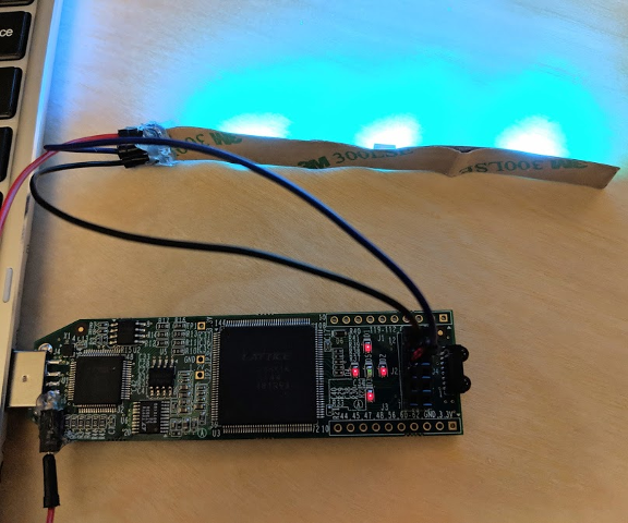
Blue Icestick
And while this post will walk through a working design, I’m sorry that it will not be a great tutorial on writing Verilog or VHDL; I will try to gloss over what I don’t understand, so I would encourage you to read a more comprehensive tutorial on the subject like Al Williams’ series of Verilog and Icestorm tutorials on Hackaday. Sorry about that, but I’m still learning and I don’t want to present misleading information. This tutorial’s code is available on Github as usual, but caveat emptor.
HDL Hell
If you’re used to writing software, Hardware Description Languages will probably take some adjusting to. I still haven’t adjusted to them so I’m not going to try to write a Verilog or VHDL tutorial, but I will try to explain the basic syntax and logic behind what I have written to run these ‘Neopixels’.
So despite my lack of knowledge, if you’re in a hurry, the 10,000-foot view is that most programming languages boil down to running one line of code after another. Sometimes CPUs will switch between programs very quickly to give the illusion that they are running multiple things at the same time, and sometimes CPUs will have multiple cores, but your program is still converted to machine code instructions which are executed one-by-one. Hardware description languages, on the other hand, are designed to describe theoretical digital circuits as a set of interconnected ‘modules’.
So if your microcontroller code is like a list of instructions describing how to do something, your FPGA code will be more like a holistic description of what you want done. This is a confusing distinction and there’s no such thing as a perfect analogy, so to avoid making things worse I’m just going to move on to a very simple example.
FPGA GPIO
People often describe FPGAs as configurable digital logic circuits. If we take that literally, then one of the simplest programs you could represent on an FPGA could be described as, “A = NOT B“. If A represents a pin connected to an LED and B represents a pin connected to a push-button, then that statement can translate to, “the LED is off when the button input is high, and on when the button input is low.”
If you were to write that program on a microcontroller, then you would need to either check the button’s state during your program’s main loop and react accordingly, or set up a hardware interrupt to jump to a different function when a rising or falling edge is detected on the button pin. The former method is usually bad practice, and the latter method still often takes around 100-1000 nanoseconds for the chip to respond.
On an FPGA, however, the two pins can essentially be hard-wired through a “NOT” logic gate, and the signal should propagate as quickly as the charge carriers can travel. This example will not use any clock signal at all, which should explain why it doesn’t necessarily make sense to ask how fast an FPGA is in terms of megahertz or gigahertz. The series of Hackaday tutorials that I mentioned earlier also explores some common problems that can arise from ‘clockless’ designs, if you’re interested.
The Constraints File
Before we tell the FPGA to wire two pins together, we need to tell it which pins we want to use and what they are going to be used for. Often development boards will have buttons, oscillators, LEDs, and other widgets attached to various pins, and the “constraints file” tells your FPGA toolchain what you want to call each pin, and how to configure them.
The Icestick has five LEDs built into the board, but no buttons. So I’ll plug a button into the board’s PMOD header along with a pull-up resistor and a small filtering capacitor. Looking at the board’s pinout, the five LEDs are on pins 95 through 99, and I chose pin 87 on the PMOD connector for the button. Using only those six pins, our constraints file is very simple:
# iCEstick PCF demo file.
# LEDs.
set_io LED1 99
set_io LED2 98
set_io LED3 97
set_io LED4 96
set_io LED5 95
# Button input.
set_io BTN  87
The syntax to use a pin for GPIO is simply, set_io <pin_name> <pin_number>. And here’s how I wired the button – the left red wire is 3.3V, the middle green wire is the button signal, and the right black wire is ground:
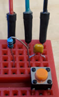
Button circuit; the resistor/capacitor values don’t really matter.
The Verilog File
We can fit this first demo circuit into a single main.v file, which will describe our program logic (A = NOT B). Although actually, to make it easier to see that the program works correctly, I’m going to set the center LED to B and the four outer LEDs to NOT B. The entire main.v file is pretty short, so I’ll copy it here before explaining each line:
`default_nettype none
module main(
  input  BTN,
  output LED1,
  output LED2,
  output LED3,
  output LED4,
  output LED5,
  );

  always
    begin
      LED1 <= ~BTN;
      LED2 <= ~BTN;
      LED3 <= ~BTN;
      LED4 <= ~BTN;
      LED5 <=  BTN;
    end
endmodule
Placing `default_nettype none at the top of the file seems to be encouraged, because it prevents the toolchain from assuming that previously-undeclared tokens should be treated as ‘wires’. If we left this line out and made a typo in one of our names (like BIN instead of BTN), the toolchain might assume that the misspelled label is supposed to be a ‘wire’, and it might quietly leave that new wire unconnected since it is not mentioned anywhere else. That can lead to all sorts of headaches, and it sounds like specifying this default ‘nettype’ tells the toolchain to treat the situation that I just described as an error.
After that, a simple module called ‘main’ is defined with one input (the button), and five outputs (the five on-board LEDs).
Inside of the module definition is a single always directive bounded with a begin / end block. I’m not too clear on Verilog control statements yet, but it seems that an always block defines logic that we want the FPGA to ensure is always true. Using <= instead of = to assign values to the LED pins tells the toolchain that the assignments are non-blocking, so LED1 will be set at the same time as LED5 despite the fact that the logic is four lines apart.
And then the actual logic operators looks a lot like C; LED1 <= ~BTN; translates to, “Set LED1 to the opposite of BTN” and LED5 <= BTN; translates to, “Set LED5 to the same value as BTN.”
The Build Process
Like I mentioned above, I’ll use the open-source Icestorm toolchain to generate a binary image for the FPGA and program it. The iCE40 line of FPGAs technically does have an on-chip non-volatile memory section for storing a configuration, but it can only ever be programmed once, so iCE40 evaluation boards like the Icestick almost always include a SPI flash memory chip which the FPGA reads from to configure itself after a reset. Keep that in mind if you intend to design hardware around these chips.
Building a binary image for the FPGA involves three steps: synthesis, ‘place-and-route‘, and ‘packing’. I won’t go into too much detail because I don’t understand the fine details very well, but the synthesis step checks your HDL files’ syntax and converts them into a digital logic circuit. The ‘place-and-route’ step then places each element of that circuit in the FPGA’s logic cell architecture, and figures out how to wire them together inside the chip. The ‘packing’ step takes the final processed design and puts it into a format that the FPGA can read and use to configure itself.
With only one Verilog file, the Icestorm build steps are simple. We can synthesize the design with yosys:
yosys -p "synth_ice40 -blif main.blif" main.v
Then perform the ‘place-and-route’ step using arachne-pnr (this step uses the icestick.pcf constraints file described above):
arachne-pnr -r -d 1k -p icestick.pcf main.blif -o main.txt
The -d option tells the utility what type of FPGA we are using. You can see a full list of supported boards by running arachne-pnr --help, but the 1k option specifies an iCE40LP/HX1K device; the Icestick uses a 144-pin iCE40HX1K. Finally, we can pack the design into a binary file using icepack:
icepack main.txt main.bin
If all goes well, you should end up with a main.bin file which you can flash using iceprog (after plugging your Icestick board into a USB port):
iceprog main.bin
Once the program finishes uploading, you should see the five LEDs reflect the state of the specified input pin; if it is high, the center green LED will be on. If it is low, the outer four red LEDs will be on. With this proof that our toolchain works, let’s move on to lighting up some ‘Neopixel’ LEDs.
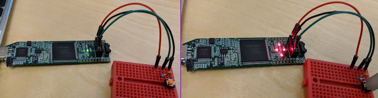
The test program with the button un-pressed and pressed.
What is a “Neopixel”?
With that basic ‘hello world’ example behind us, let’s move on to an individually-adressable RGB LED. These are colloquially called “Neopixels”, a term which Adafruit coined and which is often confusing because it has become a stand-in for all kinds of colorful programmable LEDs. For this example, I will use actual “Neopixels”, specifically SK6812 or WS2812B LEDs. They share the same timing protocol, pinout, and 5x5mm package, but I have observed that the WS2812B seems to respond to a much shorter “latching” time than the SK6812.
The WS2812B datasheet has the pin descriptions and timing diagrams.
This timing-based protocol is nice and efficient, because it is fairly high-speed while only using a single GPIO pin for communication. And while they are advertised as requiring 5V, in reality they can run off of a single lithium cell (3.7V – 4.2V) and they will work with 3.3V data signals. But you can’t quite get away with powering them off of 3.3V and the Icestick lacks a 5V output pin, so I soldered and glued a socket header onto my board’s USB connector:
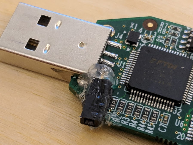
Icestick with a jury-rigged 5V connector.
Getting back to the timing, these chips want to receive 24 bits of color for each LED in the strand; 8 green, 8 red, and 8 blue. Each bit is coded as a roughly 1.25-microsecond pulse between high/low signal levels. If the signal is high for ~350ns and low for ~900ns, it is a zero. If the signal is high for ~900ns and low for ~350ns, it is a one. Once an LED has received a full 24 bits of color on its input pin, it will “shift out” any subsequent bits on its output pin, acting like a serial shift register. This lets us send as many colors as we want ‘down a line’ of LEDs, and the last color sent will be shown on the first LED in the strand.
Once we are done sending colors through the string of LEDs, we need to send a “latch” signal which tells each LED to start shining with the color that is currently occupying its shift register. The “latch” signal is sent by holding the data line low for at least 80 microseconds. I have read that WS2812B LEDs will latch after as little as 10 microseconds, but in my experience SK6812 LEDs seem to require a longer pulse in the range of 50-100 microseconds.
The Icestick has a 12MHz oscillator connected to pin 21, and we can use that to derive timings for a state machine; instead of putting our logic in an always block, we can use always@(posedge <clock_pin>) where ‘<clock_pin>’ is whatever name we give to pin 21 in our constraints file. The ‘posedge’ term means ‘positive edge’, for a block that should trigger on each rising edge of the 12MHz square wave. A 12MHz square wave will oscillate once every twelve-millionth of a second, or every 83.333 nanoseconds.
Fortunately, the ‘Neopixel’ timing could hardly work out better for our 12MHz clock signal: 83.333 * 4 = 333.33, 333.33 * 3 = 999.99, and 333.33 * 4 = 1333.33. Those values are very close to our targets of 350, 900, and 1250 nanoseconds, and they seem to work fine with the LED strips and breakout boards that I have tried so far. Those timing values are also multiples of four or sixteen clock ticks, so we can use a couple of 2-bit counters for the actual timing.
Writing a Simple State Machine
We can use a simple state machine to light up a strand of LEDs, although I suspect that this is not a great way to actually organize a Verilog project; again, I’m still learning. But the basic idea is simple: send color bits until you reach 24 bits (one full color value), then increment a counter tracking which LED you are on. If that counter is greater than the number of LEDs in the string, reset it to zero and send a ‘latch’ signal before starting over. So here’s an updated constraints file which only uses one of the PMOD pins for output and the clock pin for input:
# Simple Icestick constraints file.
# Clock
set_io clk  21
# 'Neopixel' LED strip.
set_io leds 91
Remember that the ‘clock pin’ is just an ordinary input pin connected to a 12MHz oscillator on the board. And here is the Verilog that I wound up with to send a stream of constant ‘blue/green’ colors:
`default_nettype none
module main(
  input  clk,
  output leds,
  );

  // Neopixel state machine.
  reg [2:0] state;
  reg [1:0] npxc;
  reg [12:0] lpxc;
  reg [7:0] bits;
  reg [7:0] led_num;
  reg [24:0] test_color;
  assign test_color = 24'b000111110000000000111111;
  // Process the state machine at each 12MHz clock edge.
  always@(posedge clk)
    begin
      // Process the state machine; states 0-3 are the four WS2812B 'ticks',
      // each consisting of 83.33 * 4 ~= 333.33 nanoseconds. Four of those
      // ticks are then ~1333.33 nanoseconds long, and we can get close to
      // the ideal 1250ns period.
      // A '1' is 3 high periods followed by 1 low period (999.99/333.33 ns)
      // A '0' is 1 high period followed by 3 low periods (333.33/999.99 ns)
      if (state == 0 || state == 1 || state == 2 || state == 3)
        begin
          npxc = npxc + 1;
          if (npxc == 0)
            begin
              state = state + 1;
            end
        end
      if (state == 4)
        begin
          bits = bits + 1;
    if (bits == 24)
            begin
              bits = 0;
              state = state + 1;
            end
          else
            begin
              state = 0;
            end
        end
      if (state == 5)
        begin
          led_num = led_num + 1;
          if (led_num == 96)
            begin
              led_num = 0;
              state = state + 1;
            end
          else
            begin
              state = 0;
            end
        end
      if (state == 6)
        begin
          lpxc = lpxc + 1;
          if (lpxc == 0)
            begin
              state = 0;
            end
        end
      // Set the correct pin state.
      if (test_color & (1 << bits))
        begin
        if (state == 0 || state == 1 || state == 2)
          begin
            leds <= 1;
          end
        else if (state == 3 || state == 6)
          begin
            leds <= 0;
          end
        end
      else
        begin
        if (state == 0)
          begin
            leds <= 1;
          end
        else if (state == 1 || state == 2 || state == 3 || state == 6)
          begin
            leds <= 0;
          end
      end
    end
endmodule
There’s actually not too much more to explain here; the reg keyword is used to define registers with a specified number of bits, and the assign keyword is used to define constant values such as the single unchanging 24 bits of color. I also use the blocking assignment operator (= instead of <=) when sequential logic is required between clock pulses.
But otherwise, this probably looks familiar if you are used to ‘normal programming’ with if / else statements. We also need begin / end blocks within those conditional statements, but the core logic operators like ||, <<, +, etc. behave like they do in C and most other languages.
You can build and flash this with the same commands as the previous demo program, but I also wrote a Makefile to make that process easier:
# Simple Makefile for the Icestorm FPGA toolchain.
TARGET = main
BOARD  = icestick

SYNTH  = yosys
PNR    = arachne-pnr
BIN    = icepack
PROG   = iceprog

.PHONY: all
all: $(TARGET).bin

%.blif: %.v
  $(SYNTH) -p "synth_ice40 -blif $(TARGET).blif" $(TARGET).v

%.txt: %.blif
  $(PNR) -r -d 1k -p $(BOARD).pcf $(TARGET).blif -o $(TARGET).txt

%.bin: %.txt
  $(BIN) $(TARGET).txt $(TARGET).bin

.PHONY: clean
clean:
  rm -f $(TARGET).bin
  rm -f $(TARGET).txt
  rm -f $(TARGET).blif

.PHONY: flash
flash:
  $(PROG) $(TARGET).bin
You can run make clean to clear out generated files, make or make all to build the binary image, and make flash to upload it. Once the program is uploaded, you should be able to plug in a string of ‘Neopixels’ and see them light up:
Icestick with 3 neopixels lit up in teal.
If they don’t light up, make sure that they are getting 5V of power even though the logic levels are 3.3V. Also check the actual timings on an oscilloscope; sometimes I plug things into the wrong pin, especially on the Icestick’s unlabeled PMOD connector. And I have only tested these timing values on WS2812B and SK6812 LEDs; some individually-addressable LEDs which are sold as ‘Neopixels’ use different driver chips which can have different timings or communication standards.
Conclusions
Okay, it’s still easier to use a microcontroller with a pre-written library for this sort of thing. But if I do ever need to run a hundred of these strands from a single chip, an FPGA would be a better choice. The module described above could be imported into a design many times without any loss of performance, while your average 48MHz microcontroller would choke trying to send a dozen parallel ~1MHz PWM signals, especially with the duty cycle changing after each pulse. There wouldn’t be enough timer peripherals, and the MCU would have trouble responding quickly enough to adjust the signals as they are sent in parallel.
Anyways, it was a fun project and an interesting way to learn the basics of programming an FPGA. But I am still learning, so corrections or comments would certainly be appreciated. Here’s another link to a Github repository with the code presented here, and happy holidays!

