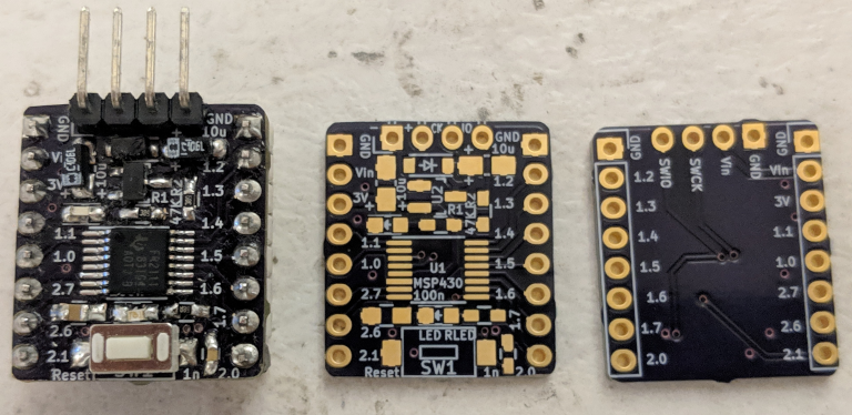
Recently, I wrote about setting up a basic ‘hello, world’ program for an MSP430 microcontroller. These chips look like they are designed to make low-power designs easy to code, so it seems like a good idea to start learning about their low-power sleep modes. TI claims that, at 3V and a 1MHz core clock speed, an MSP430x2xx will consume about 300μA while running, 55μA in “low-power mode 0”, and as little as 0.1μA in “low-power mode 4”. But you may have difficulty reaching those figures on a Launchpad board because of how the circuit is laid out.
You can see section 2.3 of the reference manual for more details on these sleep modes, but the most important thing to know is that different low-power modes can selectively disable the core CPU, system clocks, and peripherals on the chip. Some clocks and peripherals remain active in some low-power modes. For example, the chip’s timers can continue to run while the CPU is off as long as the system clock they are connected to is still active.
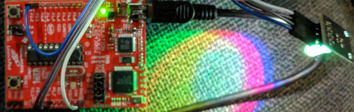
So in this tutorial, we’ll walk through pulsing a common-cathode RGB LED through various colors using the MSP430’s timers to generate PWM signals while the chip rests in LPM0 sleep mode. We need to set up the timers and attach an interrupt to periodically change the PWM duty cycles, but once that is done we can turn off the CPU. The timer interrupt will periodically wake it up, and the chip will automatically go back to sleep after the interrupt handler returns.
“Common-Cathode” LEDs let you control a red, green, and blue LED individually using PWM signals. Each LED is connected to the same cathode (‘ground’).
This post’s Github repository contains two projects; one which dims and brightens a single on-board LED using PWM, and one which uses a timer interrupt to pulse each color in a common-cathode RGB LED while putting the device to sleep when it is not active.
MSP430 Timers and PWM
The MSP430G2553 used in this tutorial has two “Timer A” peripherals, and they are fairly simple. They support the usual 16-bit timer functions; you can count up and/or down between 0x0000 – 0xFFFF, and use a set number of “capture/compare” channels to either generate PWM outputs or listen to PWM inputs. There are a few more options that you can read about in the “Timer_A” section of your reference manual, but if you’ve used a microcontroller’s timer peripheral before it will probably look familiar.
Each of the MSP430G2553’s “Timer A” peripherals has three “capture/compare” channels, but that is actually fairly limiting because we need to use one of each timer’s channels to generate a base frequency for our PWM signals. So that only leaves us with four adjustable PWM output channels in total. Also, one of Timer 0’s channels has no GPIO pins associated with its output signal. You can find this information (and more) in the “Timer_A3” section of this chip’s datasheet; page 16 as of the time of writing.
So if we want to drive three LEDs while the CPU is asleep, we’ll need to use the three timer channels with hardwired GPIO connections to power them. Each timer also has a generic interrupt which triggers whenever the timer’s counter reaches its maximum value and “ticks over”, and we can use that hardware interrupt to wake up the CPU periodically after we put it to sleep. But for now, let’s gradually dim and brighten a single LED to learn a bit about using PWM.
In the basic ‘hello world’ example, we blinked an LED by setting its GPIO pin to ‘output’ mode using a PxDIR register before toggling the pin’s state using a PxOUT register. If we want to set up a pin for use with a peripheral, the MSP430 also has two ‘mode selection’ registers which determine which peripheral a pin should connect to. For connecting a pin to a timer on the MSP430G2553, we set the appropriate bit in the PxSEL register and leave the PxSEL2 bit un-set (these settings are listed in the datasheet’s “Port Px Pin Functions” tables). So preparing P1.6 for PWM output is simple:
// Setup P1.6 for PWM output.
P1DIR  |=  (BIT6);
P1SEL  |=  (BIT6);
Then we can set up the timer peripheral, which also only takes a few lines of code:
#define MAX_TIME  (1000)
int tim = 500;

// Setup Timer 0.
TA0CCR0  = (MAX_TIME);
TA0CCTL1 = (OUTMOD_7);
TA0CCR1  = (tim);
// Start timer 0.
TA0CTL  |= (TASSEL_2 | MC_1);
The “Timer A” registers are documented in the reference manual like I mentioned at the beginning of this section, but in a nutshell, the TA0CCR0 register configures “capture/compare” channel 0 of timer 0. The MC_1 setting in TA0CTL tells the timer to count up to whatever value is stored in channel 0 before “ticking over”, so this channel will control the base frequency of our PWM signal. The TASSEL_2 setting just tells the timer to use the core system clock for its base frequency.
The TA0CCTL1 register controls “capture/compare” channel 1, which will control the duty cycle of an individual PWM signal. OUTMOD_7 sets the output mode, which you can also find more details about in the reference manual. Mode 7 alternates between setting and resetting the PWM output signal, which is good for controlling power to something like an LED. Finally, the TA0CCR1 register sets the duty cycle of the PWM signal, compared to TA0CCR0. If channel 0 is set to 1000 ticks and channel 1 is set to 500 ticks, the duty cycle will be 50% and the LED will be on half of the time.
To vary the brightness of the LED, we can adjust the duty cycle by modifying the TA0CCR1 register’s value. I think that technically you are supposed to halt the timer before changing this sort of setting, but it doesn’t really matter for a simple program like this. So here’s some simple logic to pulse the LED:
int tv = -50;

while (1) {
  tim += tv;
  if (tim > MAX_TIME) {
    tim = MAX_TIME;
    tv = -tv;
  }
  else if (tim < 0) {
    tim = 0;
    tv = -tv;
  }
  TA0CCR1 = (tim);
  delay(10000);
}
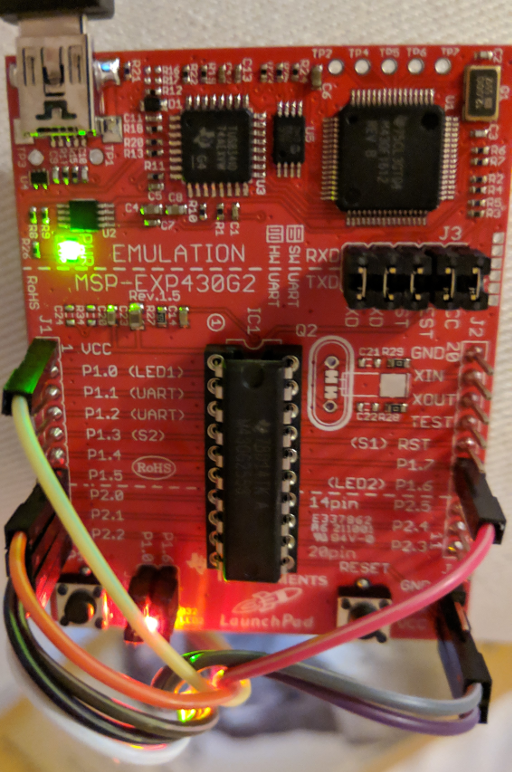
And that’s it – the full main.c file is available on Github, and if you build and flash the program to a Launchpad board it should start to smoothly pulse the LED connected to pin 1.6:
It’s not very obvious, but you can see that the red LED at the bottom of the board is dimmer than the yellow and green ones near the top, because it is being lit by PWM with a low duty cycle.
MSP430 Interrupts
That’s all well and good, but the newer MSP430G2 Launchpad boards also include a common-cathode RGB LED on the board with jumpers to pins 2.1, 2.3, and 2.5. I’m not sure why they wired it that way, because pin 2.3 connects to CCR0 in Timer 1, and like I mentioned in the previous section it looks like that channel needs to be reserved for setting a base PWM frequency. I’m probably missing something, so if you know how to control all 3 LEDs with a single timer peripheral I would love to hear about how that works.
But instead of banging my head against the wall, I connected the board’s P1.6 jumper to the P2.3 one and used Timer 0 for the green LED. If you have an old version of the board which does not have a tri-color LED built in, you can use any old 4-pin common-cathode LED board; they’re very cheap on Amazon/eBay/AliEpress/TaoBao/etc.
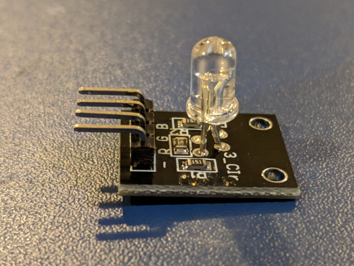
A “Common-Cathode” RGB LED board. The ‘R’, ‘G’, and ‘B’ pins connect to each LED’s anode, and the ‘-‘ pin connects to the common cathode.
Setting up the GPIO pins and timers works about the same as before, we just use more “capture/compare” channels and set the two timers’ CCR0 registers to the same value:
#define MAX_TIME  (1000)
int rv = 500;
int gv = 0;
int bv = 500;

// RGB LED Port 2 pins:
P2DIR  |=  (BIT1 | BIT5);
P2SEL  |=  (BIT1 | BIT5);
TA1CCR0  = (MAX_TIME);
TA1CCTL1 = (OUTMOD_7);
TA1CCTL2 = (OUTMOD_7);
TA1CCR1  = (rv);
TA1CCR2  = (bv);
// Start timer 1.
TA1CTL  =  (TASSEL_2 | MC_1);

// Use timer 0 for the green LED.
P1DIR  |=  (BIT6);
P1SEL  |=  (BIT6);
TA0CCR0  = (MAX_TIME);
TA0CCTL1 = (OUTMOD_7);
// Enable the Timer 0 interrupt.
TA0CTL  |= (TAIE);
TA0CCR1  = (gv);
// Start timer 0.
TA0CTL  |= (TASSEL_2 | MC_1);
The starting red/green/blue values (rv, gv, bv) are arbitrary; I set the red and blue LEDs to start at half-brightness, and the green LED to start at zero brightness. The TAIE bit in TA0CTL tells the timer to trigger a hardware interrupt when it reaches the end of its count and restarts. The hardware interrupts for your MSP430 chips will be listed in its datasheet under the “Interrupt Vector Addresses” section. In this case, we want the TIMER0_A1_VECTOR interrupt. The GCC syntax for a hardware interrupt looks like this:
#define MAX_COUNT (100)
int c = 0;

__attribute__((interrupt(TIMER0_A1_VECTOR)))
void tim0_a1_isr(void) {
  // Update the colors every N cycles.
  ++c;
  if (c >= MAX_COUNT) {
    update_colors();
    c = 0;
  }
  // Acknowledge interrupt.
  TA0CTL &= ~(TAIFG);
}
The update_colors method just applies the logic from the last PWM pulse example to each of the three LEDs; I won’t copy it all here but you can find it on Github. With an appropriate hardware interrupt defined and the peripherals all set up, we can put the chip to sleep and tell it to start listening to its hardware interrupts:
// Turn off the CPU, and enable interrupts.
_BIS_SR((LPM0_bits | GIE));

// (ZZZ...)
while (1) {}
return 0;
The _BIS_SR macro sets bits in the main status register; GIE is the “General Interrupt Enable” bit, and the chip’s maskable hardware interrupts will be ignored if it is not set. You can also disable interrupts with the corresponding ‘bit clear’ macro, _BIC_SR.
The LPM0_bits status register bits put the chip into “Low-Power Mode 0” by turning off the CPU. The system clocks will still run in LPM0 though, and so will the peripherals attached to them. Since we have set the GPIO pins to connect directly to the timer peripherals, the LEDs will continue to be lit by the rapid PWM signals that we programmed even while the CPU is sleeping.
So with that, the LEDs should start to pulse through a rainbow of colors. The CPU will also be sleeping most of the time, although the LEDs in this example program probably consume a lot more power than the microcontroller does in either run or sleep mode. Still, it’s a good learning exercise.
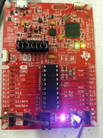
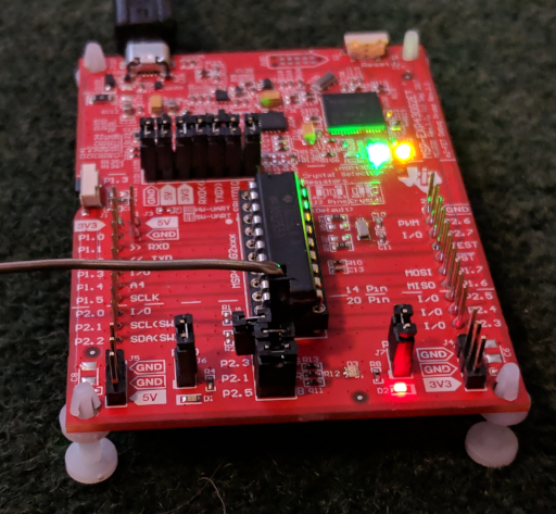
The newer Launchpad boards have an RGB LED built into the board, but this example code uses P1.6 instead of P2.3 for the green LED, so you will need to connect those pins with a jumper wire as shown here.
Conclusions
Besides the lower power consumption, this sort of example demonstrates how microcontroller programs can be entirely event-driven. If your chip has enough peripherals to associate different parts of your program with specific events or actions, you can easily conserve power by putting it to sleep when nothing important is happening. Neat!
Also, if you are reading this and you know of a good way for a hobbyist to measure very low-current applications, I would love to hear about it. There is an open-source project called “microCurrent Gold” or “μCurrent Gold” which is designed to accurately measure low-power devices, but I can’t find anywhere that still produces and distributes them. I guess that making one from the design files would be a good project in and of itself, but it’s always expensive and time-consuming to do that in quantities of one.