Most of the embedded programming that I’ve written about so far has focused on the STM32 family of ARM microcontrollers produced by ST Microelectronics. Those are a reasonable starting point for learning about microcontrollers, because they have a solid suite of open-source development tools, a decade-long history of popular use, and affordable hardware development tools which let you get started for less than $20.
But now that platforms like Arduino have become popular and presumably profitable, more vendors are getting on board with providing affordable “DIY” development tools. So while I couldn’t find any cheap and widely-available USB debuggers for TI’s MSP430 core, the “Launchpad” boards that they sell each include an on-board debugger which they say can talk to most MSP430 chips through a two-wire interface similar to the “Serial-Wire Debug” protocol used by a number of Mobile ARM cores including the STM32.
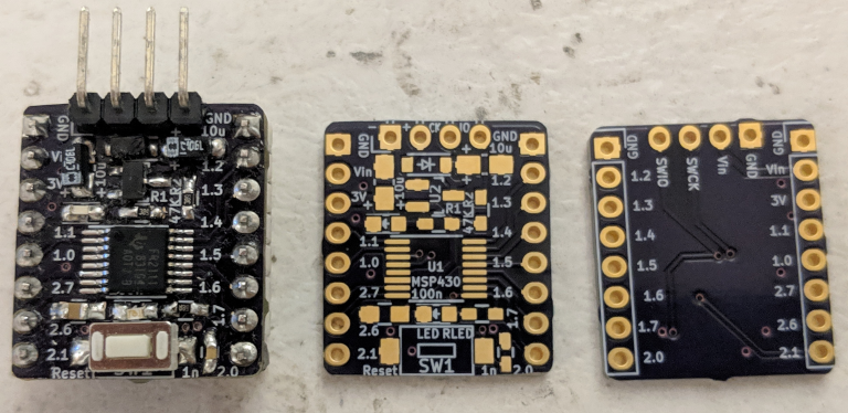
Like the Arduino Uno, some Launchpad boards use DIP chips which you can remove and plug into a breadboard once they have been programmed.
So let’s learn how to write bare-metal programs for the MSP430! This will be easier than bootstrapping a build system for the STM32, because TI opted to design a special-purpose 16-bit RISC core for these chips instead of buying a cookie-cutter core from ARM. That means that the MSP430-GCC toolchain can include ‘glue’ code like linker scripts and vector tables for every MSP430 chip ever made, and we will not need to write our own. There are also fewer steps involved in setting up clocks and peripherals, so this is a comparatively easy platform to develop on. And as usual, this tutorial’s code is on Github.
The MSP430
First, a little bit of background on the MSP430. In a nutshell, it is very similar to the original ‘Arduino’ AVR cores but with lower power consumption and 16-bit buses instead of 8-bit ones – there is even a port of the Processing IDE called Energia that targets these chips. It is still significantly slower than almost all ARM Cortex-M cores, but it can use much less power to run simple programs.
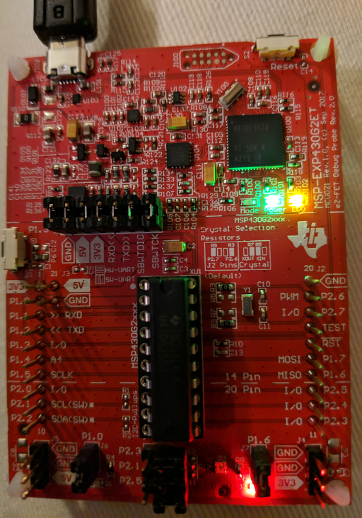
This tutorial will use an affordable ‘Launchpad’ board sod by TI. They cost about the same as ST’s ‘Nucleo’ boards – a little less than $11 – but the exact version you get will depend on when it was made. I’ll use their MSP430G2553 board, which is currently sold as the MSP-EXP430G2ET. This code will also work with an older MSP-EXP430G2 board though, and it’s pretty easy to spot the difference:
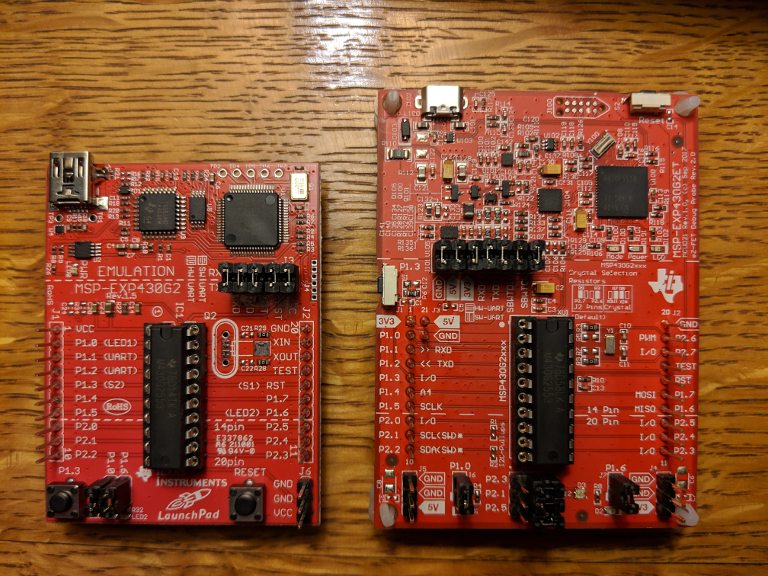
Left: the “old” board. Right: the “new” board. It’s too bad that QFP chips seem to be going out of style.
The Toolchain
It’s always nice to use open-source tools if you want to learn about how something works at a low level, and fortunately these MSP430 chips are supported by GCC and an open-source programmer/debugger. The MSPDebug utility written by dlbeer et al is very similar to the STLink utility from previous tutorials written by texane et al. It can flash binary images to MSP430 chips, and connect them to GDB sessions. Here are links to the MSP430-GCC and MSPDebug tools that you’ll need to install:
These tools might also be available from your package manager. For example, you should be able to install them in Ubuntu with a command like:
sudo apt-get install gcc-msp430 gdb-msp430 binutils-msp430 msp430mcu msp430-libc mspdebug
Be aware, however, that your package manager may have older versions of these utilities. As of the time of writing, it looks like the default Ubuntu repositories have a version of mspdebug which does not support the newer MSP430 Launchpad boards which you can buy today, and a version of gcc which does not support the newest FRAM-based chips. So you may need to manually install the most recent versions depending on which board you are using.
Blinking an LED
Like I mentioned above, the MSP430 GCC toolchain can automagically provide ‘boot code’ like linker scripts, vector tables, and startup assembly. Even better, it includes device header files for the chips, so we don’t need to go find those on the manufacturer’s site. That means that we can jump straight to a C main method, and this entire ‘Hello World’ project can fit in one brief main.c file (available on Github). The MSP430-specific lines are highlighted:
#include <msp430.h>

// (Super-simple delay method)
void delay (unsigned long int d) {
  unsigned long int i;
  for (i = 0; i < d; ++i) { asm("nop"); }
}

int main() {
  // Stop the Watchdog Timer.
  WDTCTL  =  (WDTPW + WDTHOLD);
  // Set P1.0 and P1.6 to push-pull output mode.
  P1DIR  |=  (BIT0 | BIT6);
  // Set initial LED states; one on, one off.
  P1OUT  |=  (BIT0);
  P1OUT  &= ~(BIT6);

  while (1) {
    // Toggle both LEDs, and delay a bit.
    P1OUT ^= (BIT0 | BIT6);
    delay(100000);
  }

  return 0;
}
The msp430.h header file is included with the toolchain, and it is similar to the STM32 device header files. It defines almost-legible names for the chip’s register addresses and settings; P1DIR is not exactly easy to read, but it is much nicer than (volatile uint16_t *)0x0022.
The WDTCTL register controls the chip’s watchdog timer. Most modern microcontrollers have a watchdog timer, which automatically resets the chip if it is not periodically assured that everything is working. Most modern microcontrollers also leave it turned off when the chip resets, but the MSP430 is optimized for low power usage, and there are probably a few reasons why this feature is enabled by default. Anyways, our simple program does not use the watchdog timer, so we should turn it off. The WDTPW bits are a protective ‘password’ which must be included in all writes to the ‘watchdog control’ register; if you’re interested, see the ‘Watchdog Timer+’ section of the reference manual for more details.
The P1DIR register sets the ‘direction’ of Port 1 GPIO pins, between ‘Input’ (0) and ‘Output’ (1). The MSP430’s output mode is push-pull only, but their I2C peripherals can set an open-drain mode and there may be ways to simulate that behavior.
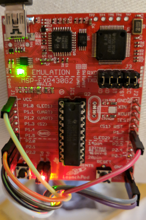
And the P1OUT register is similar to the STM32 ODR registers; it sets ‘Output’ pins to a high or low logic level. The Launchpad boards have LEDs on pins P1.0 and P1.6, so we blink the LEDs by toggling BIT0 and BIT6 in P1OUT.
Compiling and Flashing
Since there’s only one C file, we can compile it with a single command:
msp430-gcc -g -Os -Wall -mmcu=msp430g2553 -I./ -c main.c -o main.o
And a similar command links the single object file into a binary:
msp430-gcc main.o -g -mmcu=msp430g2553 -o main.elf
Finally, we can flash the program using mspdebug. This command will depend on which board you are using. For the “old” version, ask for an rf2500 interface:
sudo mspdebug rf2500 'erase' 'load main.elf' 'exit'
For the “new” version, use a tilib interface. If you get an error, you may need to build and install the msp430.so library. You might also be prompted to update your debugger’s firmware version, which you should do if and only if you are using a version of mspdebug >= 0.25 (maybe 0.24 too?):
sudo mspdebug tilib 'erase' 'load main.elf' 'exit'
The mspdebug utility acts as a REPL, but you can also pass it a series of commands to run in series. Here it erases the chip, programs it with main.elf, and then exits the utility. And if you don’t want to use sudo, the tool’s FAQ talks about how to set up USB permissions.
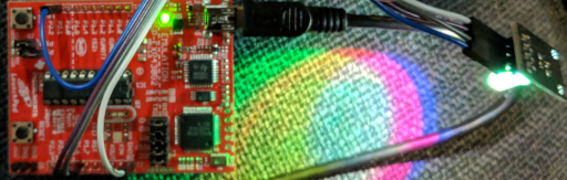
After the mspdebug command finishes, the red and green LEDs near the bottom of the Launchpad board should start to blink on and off alternatively.
The ‘P1.0’ and ‘P1.6’ LEDs should both blink on and off.
Conclusions
I haven’t done much with the MSP430 yet, but it looks like a fun chip to use. It also looks like an excellent choice for battery-powered devices because of the potential for very low power usage – it sounds like they can use less than 5 microwatts in some of its low-power standby modes at 3V.
I’m hoping to follow up on this post with a guide on using these Launchpad boards’ built-in debuggers to program a custom MSP430 board, but I won’t know if that actually works until the PCBs arrive. I’d also like to write more about low-power design, but I should probably learn more about it first.
Anyways, this looks like a worthwhile MCU core for modest applications, and I’m excited to learn more about it! Here is a link to a Github repository with the code presented here.