
In previous tutorials, I covered how to use the STM32 line of microcontrollers to draw to small displays using the SPI communication standard. First with software functions and small ‘SSD1331’ OLED displays, and then with the faster SPI hardware peripheral and slightly larger ‘ILI9341’ TFT LCD displays. Both of those displays are great for cheaply displaying data or multimedia content, because they can show 16 bits of color per pixel and have enough space to present a moderate amount of information. But if you want to design a very low-power application, you might want a display which does not need to constantly drain energy to maintain an image.
Enter ‘E-Ink’ displays, sometimes called “Electrophoretic Displays“. As the name implies, they use the same basic operating principle as techniques like Gel Electrophoresis, which separates polarized molecules such as DNA based on their electric charge. Each pixel in one of these displays is a tiny hollow sphere filled with oppositely-charged ink molecules, and they are separated between the top and bottom of their capsules to make the pixel light or dark. The ink remains in place even after power is removed; I think that they are suspended in a solid gel or something. Modern E-Ink modules sometimes have a third color such as red or yellow, but this post will only cover a humble monochrome display.
E-ink 😀
Specifically, we will go over the process of setting up and drawing to a 2.9″ E-Paper module from Waveshare. This display has a resolution of 128 x 296 pixels, so you’ll need a microcontroller with slightly more than 4KB of RAM to store a framebuffer for the display. That means that we can continue to target the affordable STM32L031K6 ‘Nucleo’ board with its 8KB of RAM, but the STM32F031K6 version which I’ve used in previous posts only has 4KB available, so this tutorial will use the STM32F042K6 (6KB) instead. Startup files like a linker script and vector table are provided in the example project on Github, but besides the fact that the project won’t link for an STM32F031K6, the code is identical.
Step 1: SPI Initialization
We’ll initialize the GPIO pins and SPI peripheral just like in the previous ILI9341 tutorial. I’ll be referring back to that tutorial a lot, since the E-Paper display uses a nearly identical protocol with the same peripheral settings. Give it a read if you’ve never used “4-wire” SPI communication before, or take a look at the simpler SSD1331 tutorial if you have never heard of “SPI communication” before. Just like those projects, our first step is to initialize the peripheral clocks and GPIO pins:
#ifdef VVC_F0
  RCC->AHBENR   |= RCC_AHBENR_GPIOAEN;
  RCC->AHBENR   |= RCC_AHBENR_GPIOBEN;
#elif  VVC_L0
  RCC->IOPENR   |= RCC_IOPENR_IOPAEN;
  RCC->IOPENR   |= RCC_IOPENR_IOPBEN;
#endif
RCC->APB2ENR |= RCC_APB2ENR_SPI1EN;
I won’t copy/paste all of the GPIO initialization code again, but you can find it in the example project on Github. The only difference between these GPIO settings and those for the ILI9341 is the addition of a BSY (‘Busy’) pin which the epaper display uses to tell us when it is busy refreshing the display and unable to listen to communications. It can take a lot of time to refresh an E-Ink display, especially with a ‘full refresh’ update, so there are points at which we will need to wait for the display to finish updating its pixels before we can send it more data.
The BSY pin should be configured as input, optionally with a pull-up resistor. The datasheet seems to say that the ‘Busy’ signal is held low while the device is busy, but this appears to be a misprint; most libraries and examples that I’ve seen delay while the pin is held high, and in my experience it does look like the display pulls the BSY pin low when it is idle.
// Configure the 'Busy' pin as input.
GPIOA->MODER   &= ~((0x3 << (PA_BUSY * 2)));
GPIOA->PUPDR   &= ~((0x3 << (PA_BUSY * 2)));
// Use a pull-up? This seems to be optional.
GPIOA->PUPDR   |=  ((0x1 << (PA_BUSY * 2)));
The SPI peripheral initialization also looks similar; I just removed most of the unnecessary bit resets, since the peripheral resets to a convenient state for this sort of communication:
/*
 * Initialize the SPI peripheral for use with a 4-wire display.
 */
void hspi_init(SPI_TypeDef *SPIx) {
  // Ensure that the peripheral is disabled, and reset it.
  SPIx->CR1 &= ~(SPI_CR1_SPE);
  if (SPIx == SPI1) {
    RCC->APB2RSTR |=  (RCC_APB2RSTR_SPI1RST);
    RCC->APB2RSTR &= ~(RCC_APB2RSTR_SPI1RST);
  }
  // Set the STM32 to act as a host device.
  SPIx->CR1 |=  (SPI_CR1_MSTR);
  // Set software 'Chip Select' pin.
  SPIx->CR1 |=  (SPI_CR1_SSM);
  // (Set the internal 'Chip Select' signal.)
  SPIx->CR1 |=  (SPI_CR1_SSI);
  // Enable the peripheral.
  SPIx->CR1 |=  (SPI_CR1_SPE);
}
Step 2: Initializing the display.
We will use the same hspi_w8 and hspi_cmd methods from the ILI9341 tutorial; the epaper display uses the same convention where a low D/C signal indicates a command, and a high D/C signal indicates data. Like the ILI9341, the ‘option’ bytes which follow most commands should be sent as data.
So, here is a basic initialization sequence mostly gleaned from Waveshare’s example project. You can also check the command descriptions in the module’s datasheet:
// Initialize a 2.9" EPaper display module.
void epd29_hspi_init(SPI_TypeDef *SPIx) {
  // Send initialization commands.
  // 'Driver output control'
  hspi_cmd(SPIx, 0x01);
  //hspi_w16(SPIx, (uint16_t)(EPD_H));
  hspi_w8(SPIx, ((EPD_H-1) % 256));
  hspi_w8(SPIx, ((EPD_H-1) / 256));
  hspi_w8(SPIx, 0x00);
  // 'Booster soft start control'
  hspi_cmd(SPIx, 0x0C);
  hspi_w8(SPIx, 0xD7);
  hspi_w8(SPIx, 0xD6);
  hspi_w8(SPIx, 0x9D);
  // 'Write VCOM register'
  hspi_cmd(SPIx, 0x2C);
  hspi_w8(SPIx, 0xA8);
  // 'Set dummy line period'
  hspi_cmd(SPIx, 0x3A);
  hspi_w8(SPIx, 0x1A);
  // 'Set gate time'
  hspi_cmd(SPIx, 0x3B);
  hspi_w8(SPIx, 0x08);
  // 'Set data entry mode setting'
  hspi_cmd(SPIx, 0x11);
  hspi_w8(SPIx, 0x03);
  // 'Set RAM area'
  hspi_cmd(SPIx, 0x44);
  hspi_w8(SPIx, 0x00);
  hspi_w8(SPIx, (uint8_t)((EPD_W-1)/8));
  hspi_cmd(SPIx, 0x45);
  hspi_w8(SPIx, 0x00);
  hspi_w8(SPIx, 0x00);
  hspi_w8(SPIx, ((EPD_H-1) % 256));
  hspi_w8(SPIx, ((EPD_H-1) / 256));
  // 'Set RAM pointer'
  hspi_cmd(SPIx, 0x4E);
  hspi_w8(SPIx, 0x00);
  hspi_cmd(SPIx, 0x4F);
  hspi_w8(SPIx, 0x00);
  hspi_w8(SPIx, 0x00);

  // 'Set Look-Up Table' settings...some defaults.
  hspi_cmd(SPIx, 0x32);
  hspi_w8(SPIx, 0x50);
  hspi_w8(SPIx, 0xAA);
  hspi_w8(SPIx, 0x55);
  hspi_w8(SPIx, 0xAA);
  hspi_w8(SPIx, 0x11);
  hspi_w8(SPIx, 0x00);
  hspi_w8(SPIx, 0x00);
  hspi_w8(SPIx, 0x00);
  hspi_w8(SPIx, 0x00);
  hspi_w8(SPIx, 0x00);
  hspi_w8(SPIx, 0x00);
  hspi_w8(SPIx, 0x00);
  hspi_w8(SPIx, 0x00);
  hspi_w8(SPIx, 0x00);
  hspi_w8(SPIx, 0x00);
  hspi_w8(SPIx, 0x00);
  hspi_w8(SPIx, 0x00);
  hspi_w8(SPIx, 0x00);
  hspi_w8(SPIx, 0x00);
  hspi_w8(SPIx, 0x00);
  hspi_w8(SPIx, 0xFF);
  hspi_w8(SPIx, 0xFF);
  hspi_w8(SPIx, 0x1F);
  hspi_w8(SPIx, 0x00);
  hspi_w8(SPIx, 0x00);
  hspi_w8(SPIx, 0x00);
  hspi_w8(SPIx, 0x00);
  hspi_w8(SPIx, 0x00);
  hspi_w8(SPIx, 0x00);
  hspi_w8(SPIx, 0x00);
  // 'Power on.'
  hspi_cmd(SPI1, 0x22);
  hspi_w8(SPI1, 0xC0);
  hspi_cmd(SPI1, 0x20);
  // Wait for the peripheral to finish sending.
  while ((SPI1->SR & SPI_SR_BSY)) {};
}
Step 3: Drawing to a Framebuffer
This is actually a pretty high-resolution display; 128 * 296 / 8 = 4736 Bytes, which is why the STM32F031K6 was not suitable for this tutorial; it only has 4KB of RAM. The display is monochrome, so each pixel only needs one bit and we’ll write 8 pixels to the display at once when we write a byte. I’ll store the framebuffer as an array of 8-bit integers (uint8_t), with dimensions based on the width and height of the display:
// Define the size of the epaper display, in pixels.
#define EPD_W     (128)
#define EPD_H     (296)
#define EPD_BYTES ((EPD_W * EPD_H) / 8)
// Declare the framebuffer.
uint8_t epd_buf[EPD_BYTES];
To test that the display works, we can define a few basic drawing methods, based on the epaper display’s settings; each byte is 8 horizontal pixels, and the vertical rows are offset by 128 / 8 = 16 bytes per row:
/*
 * Draw a single pixel to the epaper framebuffer.
 * 'C' indicates the color. For b/w displays,
 * 0 is 'black' and >= 1 is 'white'.
 */
inline void epd_draw_px(int x, int y, uint8_t c) {
  if (c) {
    epd_buf[(y * 16) + (x / 8)] |=  (1 << (7-(x % 8)));
  }
  else {
    epd_buf[(y * 16) + (x / 8)] &= ~(1 << (7-(x % 8)));
  }
}

/*
 * Draw a horizontal line to the epaper framebuffer.
 */
void epd_draw_hline(int x, int y, int w, uint8_t c) {
  // Draw pixels until the 'x' coordinate is byte-aligned.
  while (x % 8 != 0) {
    epd_draw_px(x, y, c);
    ++x;
    --w;
  }
  // Draw one byte at a time.
  while (w >= 8) {
    if (c) {
      epd_buf[(y * 16) + (x / 8)] = 0xFF;
    }
    else {
      epd_buf[(y * 16) + (x / 8)] = 0x00;
    }
    w -= 8;
    x += 8;
  }
  // Draw trailing pixels.
  while (w >= 0) {
    epd_draw_px(x, y, c);
    ++x;
    --w;
  }
}

/*
 * Draw a vertical line to the epaper framebuffer.
 */
void epd_draw_vline(int x, int y, int h, uint8_t c) {
  // Draw the appropriate bitmask down the vertical length.
  while (h >= 0) {
    epd_draw_px(x, y, c);
    ++y;
    --h;
  }
}

/*
 * Draw a rectangle to the epaper framebuffer.
 */
void epd_draw_rect(int x, int y, int w, int h, int o, uint8_t c) {
  // The 'o' argument lets the user draw an outline around the
  // area, of 'o' pixels. If 'o' is <= 0, the full area is filled.
  if (o <= 0) {
    // If the width is > the height, draw horizontal lines.
    if (w > h) {
      while (h >= 0) {
        epd_draw_hline(x, y, w, c);
        ++y;
        --h;
      }
    }
    // Otherwise, draw vertical lines.
    else {
      while (w >= 0) {
        epd_draw_vline(x, y, h, c);
        ++x;
        --w;
      }
    }
  }
  else {
    // Draw an outline.
    while (o > 0) {
      // Top.
      epd_draw_hline(x, (y + (o - 1)), w, c);
      // Bottom.
      epd_draw_hline(x, (y + h - (o - 1)), w, c);
      // Left.
      epd_draw_vline((x + (o - 1)), y, h, c);
      // Right.
      epd_draw_vline((x + w - (o - 1)), y, h, c);
      --o;
    }
  }
}
With those methods defined, we can draw a few concentric rectangles to test things:
uint8_t epd_color_byte = 0x00;
epd_draw_rect(0, 0, (EPD_W - 1), (EPD_H - 1), 0, ~epd_color_byte);
epd_draw_rect(0, 0, (EPD_W - 1), (EPD_H - 1), 2, epd_color_byte);
epd_draw_rect(4, 4, (EPD_W - 9), (EPD_H - 9), 4, epd_color_byte);
epd_draw_rect(16, 16, (EPD_W - 33), (EPD_H - 33), 6, epd_color_byte);
Step 4: Drawing to the Display
With some pixels in the framebuffer, drawing to the epaper display is very similar to drawing to the OLED or TFT display. The initialization method already set the display area to cover the whole screen, so all we have to do is send a ‘write to display RAM’ command, followed by the 4736 bytes of display data. But since epaper displays can take awhile to update, the display won’t actually change until we send another series of commands:
// Send the 'write to RAM' command.
hspi_cmd(SPI1, 0x24);
// Write to the actual RAM.
for (epd_iter = 0; epd_iter < (EPD_BYTES); ++epd_iter) {
  hspi_w8(SPI1, epd_buf[epd_iter]);
}
// Tell the epaper display to update.
// 'Display update control 2'
hspi_cmd(SPI1, 0x22);
hspi_w8(SPI1, 0xC4);
// 'Master activation'
hspi_cmd(SPI1, 0x20);
// Wait for the peripheral to finish sending.
while ((SPI1->SR & SPI_SR_BSY)) {};
// Wait for the epaper display to finish.
while ((GPIOA->IDR & (1 << PA_BUSY))) {};
// 'Terminate frame r/w'
hspi_cmd(SPI1, 0xFF);
// Wait for the epaper display to finish.
while ((GPIOA->IDR & (1 << PA_BUSY))) {};
// Invert the color being written.
epd_color_byte = !(epd_color_byte);
With the ‘full update’ LUT setting that we used in the initialization (it was a default used in the example code from Waveshare), the display will flash on and off a couple of times before settling on the image we sent to the display. It does this to make sure that there aren’t any colors left ‘burnt in’ from a previous update, but that is beyond the scope of this tutorial.
After running the initialization code, setting some starting values in your framebuffer, and drawing those values to the display, it should refresh with your image:
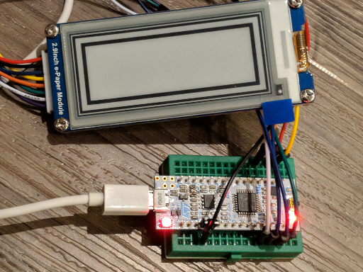
Rectangles drawn to the Eink display.
Conclusions
These displays are fun for all kinds of reasons. Apparently they are often used as displays on store shelves, and they are promising for low-power applications which don’t need to update their displayed information very often. And while I haven’t had a chance to play with the partial refresh modes yet, it sounds like you can get some cool effects by playing around with those. Here’s a link to an example project again, and I hope this has been helpful!

