
As you start to create microcontroller projects with more complicated logic, it probably won’t take long before you to want to add some sort of time-based functionality. How should you ask your chip to do something on a schedule?
These days, we don’t have to count clock cycles in ‘delay’ methods. The STM32 line of chips have a variety of “timer” peripherals available, and they are flexible enough to use for all kinds of different things. The “advanced control” timer peripheral is particularly complicated and I won’t try to cover it in this quick overview, but the basic and general-purpose timers are easy to get started with for simple counters and interrupts.
In this tutorial, we will write code to enable a hardware interrupt triggered by a timer peripheral, and use that to blink an LED. Just like the last couple of posts in this series, the STM32F031K6 and STM32L031K6 chips will be used to demonstrate these concepts. Since this tutorial will only use a single LED, you won’t need anything other than an affordable “Nucleo” board with one of those chips and a micro-USB cable:
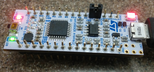
You don’t even need a breadboard!
You can double-check that the clock speeds are what we expect by counting the LED’s on/off timings against a clock. It should change about 60 times every minute with the timer set to 1 second, although the internal oscillator is not quite as precise as an external “HSE” crystal oscillator would be. As usual, an example project demonstrating this code is available in a Github repository.
The System Clock
Before you actually write code to initialize a timer, you need to understand a little bit about the STM32’s core system clock. These timer peripherals use the system’s core clock signal to derive their timings by default, so it is important to know how fast the chip is running when you configure them.
To explain the system clock’s initialization in more detail, let’s look at some basic logic to get the chip running at its maximum speed; this can go at the beginning of the ‘main’ C method, if we’re okay with the initial assembly startup code running at the chip’s default speed. The F0 and L0 lines have slightly different clock configurations, but I will highlight those differences when they come up.
Clock Sources
The core clock signal is what drives the program logic on a microcontroller. Every time that the clock signal switches between a high and low signal level, an instruction can be run by the processor. There are several types of clock source that you can use, including some “external” sources like crystal oscillators or signal generators.
When the STM32 first starts up or is reset, the chip automatically selects an 8MHz “HSI” (High-Speed Internal) oscillator on an STM32F0 chip, or a 2.1MHz “MSI” (Multi-Speed Internal) oscillator on an STM32L0 chip. STM32L0 chips also have a 16MHz HSI oscillator, but it is turned off by default. In this tutorial, we’ll use the HSI oscillators to drive the STM32’s “PLL” (Phase-Locked Loop) clock at the maximum speed allowed on the chip – 48MHz for an STM32F0 or 32MHz for an STM32L0.
Don’t worry if you don’t remember all of those acronyms – you can ‘Ctrl+F’ for them in the datasheets or reference manuals when you need a refresher. Even the 3-letter ones like “HSI” and “PLL” are usually pretty unique. It’s a good idea to save your chips’ reference manuals and datasheets for future reference; here is the manual for most STM32F0 chips, and here is the manual for STM32L0x1 chips.
Besides searching for keywords, the table of contents is also a good starting point, and you can find a lot of good information about the chip’s clock sources in the “Clocks” section of the RCC chapter (Section 6.2 in the F0 manual and Section 7.2 in the L0 manual.)
Flash Memory Latency
As you probably know by now, the STM32 stores its programs in nonvolatile ‘Flash’ memory for most simple projects. This is similar to the sort of memory used in USB thumb drives, and it sounds like the chips can reliably read data from it at a maximum speed of about 24MHz. What that means is that if our chip will be running faster than 24MHz, we need to tell it to slow down for one or more ‘wait states’ when it needs to retrieve data from memory.
On STM32F0 chips, we can do that by setting the LATENCY bits in the FLASH_ACR (Access Control Register) to the number of ‘wait states’ that we want to use. For <=24MHz, we can use the default 0 wait states. For 24-48MHz, we need to use at least 1 wait state. For 48-72MHz, at least 2 wait states are required. It goes on like that, but since the fastest speed on these chips is 48MHz, we can use a single wait state for both the STM32L0 and STM32F0 lines.
There is also a PRFTBE bit, which enables the “Flash Prefetch Buffer”. This fetches a handful of instructions at once from the Flash memory, to blunt the impact of waiting on the 24MHz flash memory access. It is a very small buffer on these small chips, but every little bit helps, so I’ll use it.
The STM32L0 line is a bit different, but it mostly has the same core options. The LATENCY (‘number of wait states’) field is just a single bit, and the “Enable Prefetch” bit is called PRFTEN. There is also a PRE_READ bit in STM32L0 chips, which looks like it tells the chip to start fetching the next instruction from Flash before the current one is done executing.
So here is some example code for setting up the FLASH_ACR register for a 32-48MHz clock speed:
#ifdef VVC_F0
  // Reset the Flash 'Access Control Register', and
  // then set 1 wait-state and enable the prefetch buffer.
  // (The device header files only show 1 bit for the F0
  //  line, but the reference manual shows 3...)
  FLASH->ACR &= ~(0x00000017);
  FLASH->ACR |=  (FLASH_ACR_LATENCY |
                  FLASH_ACR_PRFTBE);
#elif VVC_L0
  // Set the Flash ACR to use 1 wait-state
  // and enable the prefetch buffer and pre-read.
  FLASH->ACR |=  (FLASH_ACR_LATENCY |
                  FLASH_ACR_PRFTEN |
                  FLASH_ACR_PRE_READ);
#endif
Remember that the VVC_F0 or VVC_L0 options are set in the Makefile depending on which line of chip the program is being built for.
Frequency Multiplication and Division
To get a specific frequency out of the Phase-Locked Loop peripheral, we need to tell it a few things about the signal that we want to generate:
- What clock source should the PLL use for its base signal?
- How much should the PLL multiply that signal’s frequency by?
- (Sometimes optional) How much should the PLL divide that signal’s frequency by?
Which Clock Source?
The STM32F0 line has four options for the PLL clock source:
HSI / 2: The PLL’s core clock source is set to the HSI oscillator divided by 2, which is 4MHz. With this option selected, you don’t need to select a specific division factor.HSI / PREDIV: Similar to theHSI / 2option, but the HSI signal is divided by the value in thePREDIVbits ofRCC_CFGR2.HSE / PREDIV: The “HSE” (High-Speed External) oscillator is used as the PLL’s base signal, after being divided by thePREDIVbits ofRCC_CFGR2.HSI48 / PREDIV: Some of the more advancedSTM32F0chips have a 48MHz HSI oscillator built in, and that can be selected as a core source for the PLL. But theSTM32F031K6used in this tutorial does not have an HSI48 oscillator.
I’ll use the HSI / 2 signal, to get a nice and round 4MHz signal which we can multiply by 12 to get 48MHz.
The STM32L0 line has two options for the PLL clock source:
HSI16: The 16MHz “HSI” oscillator is used as the PLL core clock source, divided by a factor set by thePLLDIVbits in theRCC_CFGRregister.HSE: The “HSE” oscillator is used as the PLL core clock source, after being divided by a factor set by thePLLDIVbits.
I’ll use the HSI16 signal, divide by the minimum factor of 2, and then multiply that by 4 to get 32MHz.
Signal Multiplication and Division
In the STM32F0 line, the PREDIV values in the RCC_CFGR2 register are used to automatically divide the selected clock signal by a certain factor. Using the HSI / 2 option for the PLL’s clock source lets us ignore these bits by using a constant division factor of 2, though – see the “RCC” peripheral section of your chip’s reference manual for more details.
In the STM32L0 line, there is no RCC_CFGR2 register and no PREDIV bits. Instead, the PLL source is always divided by the PLLDIV bits in the RCC_CFGR register. The lowest allowable PLLDIV value is 2, so we can’t simply take the HSI oscillator’s 16MHz signal and multiply it by 2 to get 32MHz.
In both the STM32F0 and STM32L0 lines, once the division settings are chosen, the final PLL signal is created by multiplying the post-division frequency by the PLLMUL bit settings in the RCC_CFGR register. The actual bit values do not necessarily correspond to the same multiplication factors across STM32 lines, so check the “RCC Registers” section of your chip’s reference manual if you want to better understand the device header files’ macro definitions.
That might sound like a complicated process. but the basic equation is very simple:
PLL_frequency = (input_frequency / PLL_division) * PLL_multiplication
On the STM32F031K6 our values will be:
48MHz = (8MHz / 2) * 12
And on the STM32L031K6 it will be:
32MHz = (16MHz / 2) * 4
Initializing and Enabling the PLL
Following the above steps, here is some example C code to initialize the PLL to 48MHz on the STM32F031K6, or 32MHz on the STM32L031K6.
#ifdef VVC_F0
  // Configure the PLL to (HSI / 2) * 12 = 48MHz.
  // Use a PLLMUL of 0xA for *12, and keep PLLSRC at 0
  // to use (HSI / PREDIV) as the core source. HSI = 8MHz.
  RCC->CFGR  &= ~(RCC_CFGR_PLLMUL |
                  RCC_CFGR_PLLSRC);
  RCC->CFGR  |=  (RCC_CFGR_PLLSRC_HSI_DIV2 |
                  RCC_CFGR_PLLMUL12);
  // Turn the PLL on and wait for it to be ready.
  RCC->CR    |=  (RCC_CR_PLLON);
  while (!(RCC->CR & RCC_CR_PLLRDY)) {};
  // Select the PLL as the system clock source.
  RCC->CFGR  &= ~(RCC_CFGR_SW);
  RCC->CFGR  |=  (RCC_CFGR_SW_PLL);
  while (!(RCC->CFGR & RCC_CFGR_SWS_PLL)) {};
  // Set the global clock speed variable.
  core_clock_hz = 48000000;
#elif VVC_L0
  // Enable the HSI oscillator, since the L0 series boots
  // to the MSI one.
  RCC->CR    |=  (RCC_CR_HSION);
  while (!(RCC->CR & RCC_CR_HSIRDY)) {};
  // Configure the PLL to use HSI16 with a PLLDIV of
  // 2 and PLLMUL of 4.
  RCC->CFGR  &= ~(RCC_CFGR_PLLDIV |
                  RCC_CFGR_PLLMUL |
                  RCC_CFGR_PLLSRC);
  RCC->CFGR  |=  (RCC_CFGR_PLLDIV2 |
                  RCC_CFGR_PLLMUL4 |
                  RCC_CFGR_PLLSRC_HSI);
  // Enable the PLL and wait for it to stabilize.
  RCC->CR    |=  (RCC_CR_PLLON);
  while (!(RCC->CR & RCC_CR_PLLRDY)) {};
  // Select the PLL as the system clock source.
  RCC->CFGR  &= ~(RCC_CFGR_SW);
  RCC->CFGR  |=  (RCC_CFGR_SW_PLL);
  while (!(RCC->CFGR & RCC_CFGR_SWS_PLL)) {};
  // Set the global clock speed variable.
  core_clock_hz = 32000000;
#endif
Notice how the device header macro definitions are used. In the STM32F0 logic, the RCC_CFGR_PLLMUL macro covers all of the bits in the PLLMUL field, so resetting its bitwise opposite sets the entire field to 0 in the register. Then, the RCC_CFGR_PLLMUL12 setting has the value for multiplying by 12 in the specific chip being used.
It is possible that those settings will be represented by different values on a chip other than the STM32F031K6, so using the device header files’ definitions instead of raw hex values helps you to write code which works across the whole line of STM32F0 chips, and sometimes even the whole family of STM32s.
Once the clock speed is set up, it is a good idea to store the current system clock frequency in a global variable; I’ll use a uint32_t core_clock_hz in this tutorial.
Using a Timer Peripheral
With the core system clock set to a known frequency, we can use the chip’s built-in “timer” peripherals to trigger actions at fairly precise timing intervals. The timer peripherals can perform a variety of time-based actions, and there are good explanations in the reference manuals. I would recommend reading about the basic and general-purpose timers before braving the complicated “Advanced Control” timer (called TIM1).
You can also check your chip’s reference manual for more information about the timer peripherals. TIM2, which I’ll use in this tutorial, is covered in Section 16 of the STM32L0 reference manual and/or Section 18 of the STM32F0 reference manual.
Enabling the Peripheral
While I’ll use the TIM2 general-purpose timer as an example, it looks like the other “general-purpose” timers like TIM14, TIM16, and TIM17 are exactly the same. The STM32F031K6 has all three of those available, but the STM32L031K6 does not.
The first step is to enable the peripheral in its RCC register. TIM2 and TIM14 are in the APB1 clock domain, so we’ll use APB1ENR to enable them and APB1RSTR to reset them. If you were using TIM16 or TIM17, you’d want to use the APB2 registers instead. And the NVIC interrupts are set up in the same way that we set up the EXTI ‘button press’ interrupts in the last tutorial:
// Enable the TIM2 clock.
RCC->APB1ENR |= RCC_APB1ENR_TIM2EN;
// Enable the NVIC interrupt for TIM2.
NVIC_SetPriority(TIM2_IRQn, 0x03);
NVIC_EnableIRQ(TIM2_IRQn);
Setting a ‘Counter’ Interrupt
With the peripherals enabled and the NVIC hardware interrupt enabled, it is fairly simple to set a timer interrupt to trigger every N milliseconds using the timer’s counter. You’ll only need to use 6 timer registers:
CR1: ‘Control Register 1’ – this register is used to enable and disable the peripheral.CNT: ‘Counter Register’ – this register hold’s the timer’s current counter value. It counts up from 0 once the timer is started.PSC: ‘Prescaler Register’ – this register will hold the timer’s prescaler. A prescaler value ofNwill tick the timer’s counter register up by one everyN+1clock cycles.ARR: ‘Autoreload Register’ – the autoreload value is the ‘period’ of the timer. An autoreload value ofNwill cause the timer to trigger an update event every time theCNTregister counts up toN.EGR: ‘Event Generation Register’ – Setting theUGbit in this registers resets all of the timer’s counters and tells it to use the currently-set prescaler/autoreload values.DIER: ‘DMA/Interrupt Enable Register’ – Setting theUIEbit in this register sets the timer to trigger a hardware interrupt when an update event occurs. Usually, that happens when the ‘Counter’ register matches the ‘Autoreload’ value.SR: ‘Status Register’ – TheUIFflag is set in this register when a timer’s hardware interrupt triggers, and must be cleared before another one can occur.
We’ll set the ‘Prescaler’ so that the timer counts up every millisecond, and then set the ‘Autoreload’ value to however many milliseconds the timer should measure. Then we’ll set the EGR_UG bit to apply those settings, the DIER_UIE bit to enable an interrupt, and start the timer:
void start_timer(TIM_TypeDef *TIMx, uint16_t ms) {
  // Start by making sure the timer's 'counter' is off.
  TIMx->CR1 &= ~(TIM_CR1_CEN);
  // Next, reset the peripheral. (This is where a HAL can help)
  if (TIMx == TIM2) {
    RCC->APB1RSTR |=  (RCC_APB1RSTR_TIM2RST);
    RCC->APB1RSTR &= ~(RCC_APB1RSTR_TIM2RST);
  }
  #ifdef VVC_F0
  else if (TIMx == TIM14) {
    RCC->APB1RSTR |= (RCC_APB1RSTR_TIM14RST);
    RCC->APB1RSTR &= ~(RCC_APB1RSTR_TIM14RST);
  }
  else if (TIMx == TIM16) {
    RCC->APB2RSTR |=  (RCC_APB2RSTR_TIM16RST);
    RCC->APB2RSTR &= ~(RCC_APB2RSTR_TIM16RST);
  }
  else if (TIMx == TIM17) {
    RCC->APB2RSTR |=  (RCC_APB2RSTR_TIM17RST);
    RCC->APB2RSTR &= ~(RCC_APB2RSTR_TIM17RST);
  }
  #endif
  // Set the timer prescaler/autoreload timing registers.
  // (These are 16-bit timers, so this won't work with >65MHz.)
  TIMx->PSC   = core_clock_hz / 1000;
  TIMx->ARR   = ms;
  // Send an update event to reset the timer and apply settings.
  TIMx->EGR  |= TIM_EGR_UG;
  // Enable the hardware interrupt.
  TIMx->DIER |= TIM_DIER_UIE;
  // Enable the timer.
  TIMx->CR1  |= TIM_CR1_CEN;
}
Note that these timers are 16-bit, so the maximum values allowed in the Prescaler and Autoreload registers is 65,535. That means that this timer method won’t work for clock speeds higher than about 65MHz, or delays longer than about a minute (60,000 milliseconds).
Blinking the Onboard LED
You can initialize the on-board LED pin just like in the past couple of tutorials, and toggle it in the timer interrupt using the ^ (“XOR”) operator. Remember that the SR ‘Status’ register needs to be cleared to let future interrupts trigger, so this is what an example interrupt handler might look like:
void TIM2_IRQ_handler(void) {
  // Handle a timer 'update' interrupt event
  if (TIM2->SR & TIM_SR_UIF) {
    TIM2->SR &= ~(TIM_SR_UIF);
    // Toggle the LED output pin.
    GPIOB->ODR ^= (1 << LED_PIN);
  }
}
You can see how these methods are declared and used in the example Github repository, but it’s fairly simple once you understand the registers. Also, stopping one of these timers after it is started is very easy:
void stop_timer(TIM_TypeDef *TIMx) {
  // Turn off the timer.
  TIMx->CR1 &= ~(TIM_CR1_CEN);
  // Clear the 'pending update interrupt' flag, just in case.
  TIMx->SR  &= ~(TIM_SR_UIF);
}
Conclusions
Besides performing actions on a consistent schedule, these timer peripherals are also a good way to make fairly accurate ‘delay’ or ‘sleep’ methods. You can start a timer for the time that you want to delay, wait for a variable to be set in the interrupt handler, and then stop the timer. Or, you can skip setting up the hardware interrupt and check the timer’s CNT register in a while loop.
Timers are a fundamental part of many embedded systems, so it’s good to get a basic feel for these peripherals early on. As usual, an example project demonstrating the code in this tutorial is available on Github.
I’m hoping to cover some more advanced timer functionality like PWM and input capture in a future post. I’d also like to learn and write a bit more about the ‘SysTick’ peripheral, which is a simple 24-bit timer available on most ARM Cortex-M cores. It seems like a good way to run recurring logic on a schedule, and I think that it might be a common way for RTOS systems to drive schedule timings.


Mark
May 6, 2020 at 6:20 am
There are a few errors/typos in this one. Easy enough to sort out if you’re paying attention as a reader, but FYI:
Under the “Enabling the peripheral” heading, in the example code you have:
NVIC_SetPriority(TIM2_IRQn, 0x03);
NVIC_EnableIRQ(TIM2_RQn);
TIM2_RQn should be TIM2_IRQn in the last line. Also under “Enabling the Peripheral” it says “TIM2 and TIM14 are in the APB1 clock domain, so we’ll use APB1ENR to reset them and APB1RSTR to reset them.” I assume that should say “we’ll use APB1ENR to enable them and APB1RSTR to reset them.”
Under the “Setting a ‘Counter’ Interrupt” heading, in the example code you have:
#ifdef VVC_F0
else if (TIMx == TIM14) {
RCC->APB1RSTR |= (RCC_APB2RSTR_TIM14RST);
RCC->APB1RSTR &= ~(RCC_APB2RSTR_TIM14RST);
}
Those macros should be RCC_APB1RSTR_TIM14RST (1 instead of a 2).
I can’t thank you enough for writing these articles. I bought my first STM32 dev board probably 2 years ago, maybe more. I tried and tried to find a good resource for learning and had trouble with all of the bare metal guides I’ve found. There were some SPL guides that looked good but that seemed to be deprecated so I didn’t want to learn that way. I probably could have learned with some HAL guides that are out there but in addition to obfuscating what’s actually going on when using HAL, I find learning it to be equally if not more difficult than just learning how to do this stuff by setting the registers. This is by far the most helpful bare metal guide I’ve come across, and it finally has me doing some things w/ STM32 after I’d gotten extremely frustrated and just set them aside for years, and you explain what’s happening very well so I feel like I’m really learning this stuff rather than just copying code.
Vivonomicon
June 6, 2020 at 12:18 pm
Oh, you’re right – thank you for the corrections! I’ve fixed those typos, sorry that they slip in sometimes.
And thank you for the kind words – it’s really nice to hear that these posts are helpful, and I hope you continue to enjoy learning about embedded development.
Adam
June 13, 2020 at 5:13 am
Nice tutors.
I’ve been looking for a solution to generate 180degree pwm phase shift on stm32f0 .
No solution yet, you have any idea ??
Vivonomicon
July 3, 2020 at 11:09 am
Sorry, I don’t have any ideas about that. But the reference manuals do say that it is possible to synchronize timer peripherals so they start running at the exact same time. Check out the “Basic Timers” and “General-Purpose Timers” chapters; the “Advanced-Control Timers” might also be able to do what you want, but those peripherals are moree complicated and it’ll be easier to read that chapter once you understand the basic timers.
Good luck!