
Time may be an artificial construct, but try telling your boss that ‘Monday’ has no meaning. It is useful for a program to be able to schedule actions for a certain date, display the current time on a clock or calendar, or perform other tasks which use weird units of time like ‘seconds’ or ‘days’. For those types of tasks, an embedded developer might reach for an ‘RTC’ device, which stands for ‘Real-Time Clock’. They provide a way to keep accurate time, often with features like backup power supplies. Many RTCs also offer ‘wakeup’ alarms for other devices, so they are especially useful in energy-efficient designs.
The STM32 line of chips which I’ll continue to use in this tutorial have a built-in RTC peripheral, but they require an external 32.768KHz ‘LSE’ (Low-Speed External) crystal oscillator to keep accurate time. Also, managing the STM32’s backup power supply is sort of complicated.
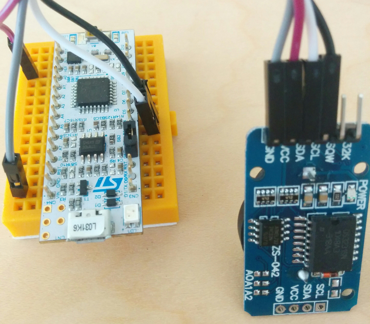
Instead, this tutorial will walk through using the ‘I2C’ peripheral on an STM32 chip to communicate with a cheap DS3231 RTC module. Specifically, I will talk about a widely-available board labeled ZS-042, which includes 4KB of EEPROM on its I2C bus and space for a “coin cell” battery to provide several years of backup power. But the same commands should work with other DS3231 boards, such as the smaller ones in the upper-left here:
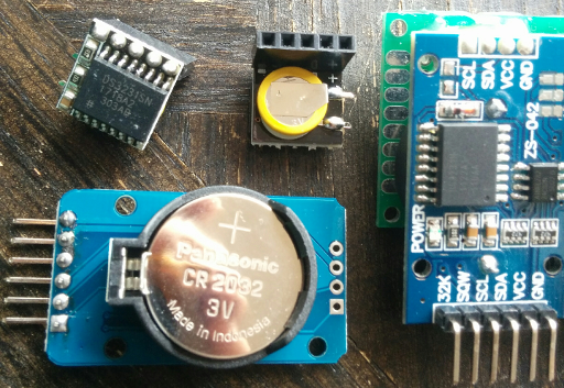
A handful of DS3231 modules and their backup batteries.
An example project demonstrating the concepts outlined in this post using either an STM32F031K6 or STM32L031K6 “Nucleo” board is available on Github.
The ZS-042
So, before we do anything to these boards – including plugging them in – let’s take a look at them.
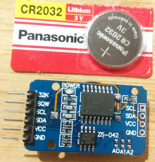
ZS-042 Board, and the type of non-rechargeable battery most people use. Notice that the ‘VCC’ line connects to the positive battery terminal.
There is a problem, highlighted in orange. The positive power line is connected through a 1KΩ resistor and a diode to the battery’s positive terminal. Presumably, this circuit is intended to recharge the battery when power is applied to the module. That’s great if you are using a rechargeable battery, but if you just bought some cheap “CR2032” coin cell batteries, those are probably not rechargeable. So, I would recommend removing either the diode or the nearby resistor labeled 102:
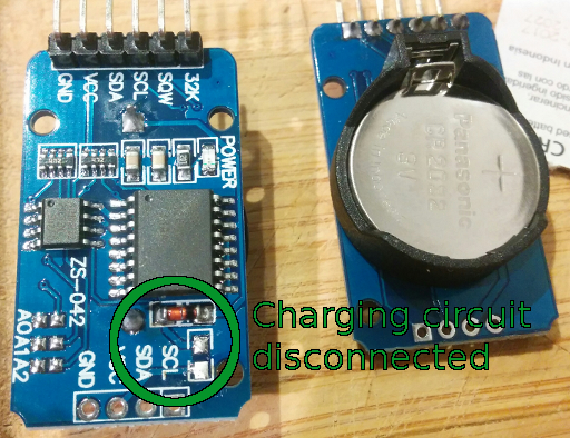
You can remove surface-mount resistors by holding a hot soldering iron against one end and pressing firmly until it melts the other side and the part slides off. Be careful!
The other thing worth noticing is that there are actually two chips on the board; one is the DS3231 RTC, but there is also an 8-pin EEPROM chip marked 24C32N which we can use to store 4KB of miscellaneous data while the power is out (the ’32’ stands for ’32 kilobits‘). We can set the EEPROM module’s I2C address with the A0, A1, and A2 jumpers.
I2C = IIC = “Inter-Integrated Circuit”
The ‘I2C’ communication standard is similar to the ‘SPI’ one discussed in my SSD1331 tutorial, but it’s a bit more complicated to write a software driver for. It is notable for being able to support several different devices on the same two wires, though, which is a nice feature. It uses “open-drain” outputs instead of “push-pull” ones, and while both the clock and data lines require ‘pull-up’ resistors, those are almost always included on the device boards.
To avoid the headache of figuring out the whole standard, we can use the STM32’s I2C hardware peripheral to manage communication. It will make our lives much easier; once the peripheral is initialized, we’ll be able to easily send and receive data using the “Transmit” and “Receive” I2C registers.
Initializing the I2C Peripheral
The STM32F0 I2C peripheral is described in section 26 of the chip’s reference manual. The first step in using the peripheral is…well, turning it on. There can be multiple I2C peripherals on an STM32 chip, but I’ll use I2C1 in this tutorial. Its ‘reset’ settings are in the RCC_APB1 registers, so to enable it:
RCC->APB1ENR |= RCC_APB1ENR_I2C1EN;
As in previous tutorials, these register macros are defined in the vendor-provided stm32f031x6.h device header file. We also need to set up the SCL and SDA GPIO pins; the I2C1 peripheral is on pins B6 and B7 in these STM32 chips (I defined some macros in the example project’s main.h file), and these F031/L031 chips map I2C1 to “alternate function” 1 for the B6/B7 pins:
/* (main.h macros) */
#define SCL_PIN (6)
#define SDA_PIN (7)
// For I2C1, use AF1.
GPIOB->AFR[SCL_PIN/8] &= ~(0xF << (SCL_PIN*4));
GPIOB->AFR[SCL_PIN/8] |=  (0x1 << (SCL_PIN*4));
GPIOB->AFR[SDA_PIN/8] &= ~(0xF << (SDA_PIN*4));
GPIOB->AFR[SDA_PIN/8] |=  (0x1 << (SDA_PIN*4));
// B6/7 should be set to 'alt' mode, open-drain, with pull-up.
GPIOB->MODER  &= ~(0x3 << (SCL_PIN*2));
GPIOB->MODER  |=  (0x2 << (SCL_PIN*2));
GPIOB->PUPDR  &= ~(0x3 << (SCL_PIN*2));
GPIOB->PUPDR  |=  (0x1 << (SCL_PIN*2));
GPIOB->OTYPER |=  (0x1 << SCL_PIN);
GPIOB->MODER  &= ~(0x3 << (SDA_PIN*2));
GPIOB->MODER  |=  (0x2 << (SDA_PIN*2));
GPIOB->PUPDR  &= ~(0x3 << (SDA_PIN*2));
GPIOB->PUPDR  |=  (0x1 << (SDA_PIN*2));
GPIOB->OTYPER |=  (0x1 << SDA_PIN);
The GPIO_AFR registers have four bits per pin, and they set which “alternate function” should be assigned to a pin if its GPIO_MODER bits are set to 0x2. I wrote about the GPIO peripheral in a previous post, but here is a quick review of the main configuration registers:
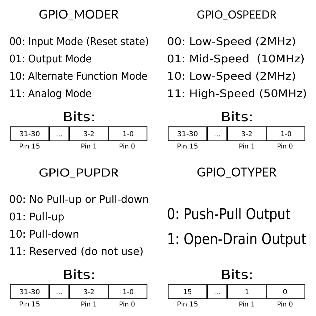
STM32F0 GPIO configuration register quick reference.
Once the pins are set up, all we have to do is set the initial configuration and ‘timing’ values for the I2C peripheral before turning it on. I’ll use 100KHz (if the core clock is 48MHz) as an example. Most devices will list a maximum speed, but this setting doesn’t matter too much if you’ll only be sending one or two bytes at a time. The timing register value came from one of ST’s application notes, but they also provide a utility to generate the right settings for your application. A few CR1 / CR2 (“Control Register”) flags are also reset for good measure:
// Initialize the I2C1 peripheral.
// First, disable the peripheral.
I2C1->CR1 &= ~(I2C_CR1_PE);
// Clear some 'CR1' bits.
I2C1->CR1 &= ~( I2C_CR1_DNF    |
                I2C_CR1_ANFOFF |
                I2C_CR1_SMBHEN |
                I2C_CR1_SMBDEN );
// Clear some 'CR2' bits.
I2C1->CR2 &= ~( I2C_CR2_RD_WRN |
                I2C_CR2_NACK   |
                I2C_CR2_RELOAD |
                I2C_CR2_AUTOEND );
// Configure I2C timing.
// Reset all but the reserved bits.
I2C1->TIMINGR &= (0x0F000000);
// (100KHz @48MHz core clock, according to an application note)
I2C1->TIMINGR |= (0xB0420F13);
// Finally, enable the peripheral. (PE = 'Peripheral Enable')
I2C1->CR1 |= I2C_CR1_PE;
You might also want to clear the flags in I2C_ICR before enabling the PE bit – that should clear any events that may have been registered if the chip didn’t get to perform a full reset for some reason.
How to Use the I2C Peripheral
Since the I2C bus supports several different devices on the same line, we need to start by defining the ‘address’ of the device we want to talk to. The DS3231 uses address 0xD0, which you can see in its datasheet. The STM32F0 I2C hardware peripheral uses the first byte of its CR2 register for storing the current device address, but we can also use the macros defined in ST’s device header files:
I2C1->CR2 &= ~(I2C_CR2_SADD);
I2C1->CR2 |=  (0xD0 << I2C_CR2_SADD_Pos);
The only other thing we need to do is tell the peripheral to send “start” and “stop” conditions before and after each communication. And when we send or receive data, we also need to tell the peripheral how many bytes of data will be transmitted, by setting bits 16-23 (NBYTES) in the I2C_CR2 register. Here are some simple methods for sending “start” and “stop” conditions using the peripheral:
inline void i2c_start(void) {
  // Send 'Start' condition, and wait for acknowledge.
  I2C1->CR2 |=  (I2C_CR2_START);
  while ((I2C1->CR2 & I2C_CR2_START)) {}
}
inline void i2c_stop(void) {
  // Send 'Stop' condition, and wait for acknowledge.
  I2C1->CR2 |=  (I2C_CR2_STOP);
  while ((I2C1->CR2 & I2C_CR2_STOP)) {}
  // Reset the ICR ('Interrupt Clear Register') event flag.
  I2C1->ICR |=  (I2C_ICR_STOPCF);
  while ((I2C1->ICR & I2C_ICR_STOPCF)) {}
}
In some registers like I2C_ICR, bits are reset when you write 1 to them, not 0; that can be a bit confusing. We can also write similar simple methods for transmitting and receiving a single byte over the peripheral. To write a byte, we write it to the I2C_TXDR (“Transmit Data Register”) and wait for the peripheral to mark the transfer as finished. To read a byte, we wait for the peripheral to mark the read as finished before reading the I2C_RXDR (“Receive Data Register”) value.
void i2c_write_byte(uint8_t dat) {
  // Send a byte of data, and wait for the transfer to finish.
  I2C1->TXDR = (I2C1->TXDR & 0xFFFFFF00) | dat;
  while (!(I2C1->ISR & (I2C_ISR_TXIS | I2C_ISR_TC))) {}
}
uint8_t i2c_read_byte(void) {
  // Wait for a byte of data to be available, then read it.
  while (!(I2C1->ISR & I2C_ISR_RXNE)) {}
  return (I2C1->RXDR & 0xFF);
}
In the i2c_write_byte method, the TXIS bit indicates that the peripheral is ready to send another byte, and the TC bit indicates that the current transfer is complete. TC is set instead of TXIS when the number of bytes sent matches the value that we set in the NBYTES bits of I2C_CR2. It is also worth noting the TXE bit, which is set whenever the I2C_TXDR (“Transmit Data Register”) register is empty.
For i2c_read_byte, we just wait for the RXNE bit which indicates that there is data ready to be read. These methods can all cause infinite loops if an expected condition is never detected; error handling is outside the scope of this tutorial.
Talking to the DS3231
As a simple example of reading and writing on the I2C bus, let’s try turning the DS3231 on. Most of these chips ship in an “off” state so that they don’t drain their backup batteries while they are in storage and shipment. To turn them on, we need to clear the “oscillator stop flag” (bit 7) in the “Control/Status” register, which has an offset of 0x0F. Just like the device’s I2C address, these values can all be found in the DS3231 datasheet – look at page 11 for a quick overview.
We’ll perform a simple ‘read / modify / store’ operation to only change a single bit in the register. First, we’ll read the current byte stored in the DS3231. Then, we’ll clear the bit that we are interested in. And finally, we’ll write the new byte back to the DS3231. This is basically the same process as modifying a normal peripheral register, but the memory is on an external device.
As mentioned in the previous section, the hardware I2C1 peripheral uses pin B6 as SCL, and pin B7 as SDA. On the ‘Nucleo-32’ boards distributed by ST, pin B6 is labeled D5 and pin B7 is labeled D4. Connect GND to one of the board’s ground pins, and VCC to a +3.3V supply:
Wiring a ‘ZS-042’ DS3231 module to an STM32 ‘Nucleo’ board.
Writing a Byte Over I2C
In order to read a register from the DS3231, we need to tell it which register we want to read from first. The “Control/Status” register’s address offset is 0x0F, so we simply need to write that one byte before asking the peripheral to read a byte of data from the device. The I2C protocol defines different signals for requesting reads and writes, and the RD_WRN bit in I2C_CR2 controls that direction. I reset that bit to 0 in the logic to initialize the peripheral, which set the starting direction to ‘write’. We’ll set it to 1 in the next section to read data.
So to send data over I2C: first set the number of bytes to send in the NBYTES bits of I2C_CR2 (just one in this case,) then write the data one byte at a time in between “start” and “stop” conditions, using the methods defined above:
// Set '1 byte to send.'
I2C1->CR2 &= ~(I2C_CR2_NBYTES);
I2C1->CR2 |=  (0x01 << I2C_CR2_NBYTES_Pos);
// Start the I2C write transmission.
i2c_start();
// Send the register address.
i2c_write_byte(0x0F);
// Stop the I2C write transmission.
i2c_stop();
Reading a Byte Over I2C
Now that we have told the DS3231 which of its registers we want to read, we can tell the I2C peripheral to listen for a byte of data from the device. Like before, we set NBYTES to the number of bytes that we expect to receive (again, just one), and then we read the data one byte at a time between “start” and “stop” conditions. We’ll also set the RD_WRN bit mentioned previously before sending a “start” condition, to read data instead of writing:
// Set '1 byte to receive.'
I2C1->CR2 &= ~(I2C_CR2_NBYTES);
I2C1->CR2 |=  (0x01 << I2C_CR2_NBYTES_Pos);
// Set 'read' I2C direction.
I2C1->CR2 |=  (I2C_CR2_RD_WRN);
// Start the I2C read transmission.
i2c_start();
// Read the transmitted data.
uint8_t read_result = i2c_read_byte();
// Stop the I2C read transmission.
i2c_stop();
// Set 'write' I2C direction again.
I2C1->CR2 &= ~(I2C_CR2_RD_WRN);
This is very similar to the ‘write’ logic – besides changing the RD_WRN bit, it just uses i2c_read_byte instead of i2c_write_byte. I put this common ‘write address / read one byte’ logic in an i2c_read_register(uint8_t address) method, which you can see in the example Github project.
With the value read, we can clear the 0x80 bit and write it back to turn the chip on – here would be an example using the ‘read_register’ method described above:
uint8_t ds3231_status = i2c_read_register(0x0F);
ds3231_status &= ~(0x80);
// Write two bytes; the register offset, and its value.
I2C1->CR2 &= ~(I2C_CR2_NBYTES);
I2C1->CR2 |=  (0x02 << I2C_CR2_NBYTES_Pos);
i2c_start();
i2c_write_byte(0x0F);
i2c_write_byte(ds3231_status);
i2c_stop();
Reading and Writing Multiple Bytes Over I2C
Sometimes you’ll want to read/write multiple bytes from/to a device. An example with the DS3231 would be checking or setting the current time, which spans several registers for values like ‘seconds’, ‘minutes’, etc. We can simply perform a single I2C transmission to interact with several contiguous bytes, starting with a write to indicate the starting address of the registers that we want to use. The NBYTES option in I2C_CR2 lets us specify how many bytes we want to read/write.
So to set the time, we can write the 7 ‘time/date’ registers in order. The order is listed in the DS3231 datasheet – starting at offset 0x00, it goes:
- Seconds
- Minutes
- Hours
- Day of the week
- Day of the month
- Month
- Year (last 2 digits)
Each value is encoded in “BCD” format, which is designed to make it easy to quickly convert into clock digits. Basically, (with some small exceptions,) each register is split into “tens” and “ones” digits, which are each a number between 0 and 9. So we can convert from decimal to BCD pretty easily:
inline uint8_t dec_to_bcd(uint8_t dec) {
  return ((((dec / 10) & 0xF) << 4) |
           ((dec % 10) & 0xF));
}
And sending 8 bytes (1 address byte + 7 time values) over I2C looks a lot like sending 1 byte:
const uint8_t seconds = 0;
const uint8_t minutes = 45;
const uint8_t hours = 13;
const uint8_t day = 29;
const uint8_t month = 4;
const uint8_t year = 18;
const uint8_t weekday = 6;
// We'll write 7 registers; one for each of the above.
// (Plus 1 for the initial register offset, 0x00).
I2C1->CR2 &= ~(I2C_CR2_NBYTES);
I2C1->CR2 |=  (0x08 << I2C_CR2_NBYTES_Pos);
i2c_start();
// (The 'seconds' register is at offset 0x00.)
i2c_write_byte(0x00);
// The registers are written and read in 'BCD' format.
i2c_write_byte(dec_to_bcd(seconds));
i2c_write_byte(dec_to_bcd(minutes));
i2c_write_byte(dec_to_bcd(hours) | 0x40);
i2c_write_byte(weekday);
i2c_write_byte(dec_to_bcd(day));
i2c_write_byte(dec_to_bcd(month));
i2c_write_byte(dec_to_bcd(year));
i2c_stop();
Reading multiple bytes works in the same way, and we’ll do that in a little bit to test the EEPROM chip. For now, the RTC registers are also read in BTC format, so we can quickly test that the clock is keeping time by checking the first four bits of the ‘seconds’ register (the ‘ones’ digit) in our main loop, and only turning on the board’s LED when it is equal to zero:
// Main loop.
uint8_t cur_s = 0;
while(1) {
  cur_s = i2c_read_register(0x00);
   // Turn the board's LED on every tenth second.
  if ((cur_s & 0x0F) == 0) {
    GPIOB->ODR |= (1 << LED_PIN);
  }
  else {
    GPIOB->ODR &= ~(1 << LED_PIN);
  }
}
In other words, the LED should turn on every ten seconds, for a full second.
Talking to the EEPROM
The EEPROM chip looks like an AT24C32N, or something similar. It can store 4KB of data which will not get erased between power cycles. Reading and writing to its memory works almost exactly the same as reading and writing to the DS3231 registers. The only difference is that the memory addresses are 12 bits long, so we need to send two bytes of data instead of one to mark the starting address for a read or write.
The device address is listed in the datasheet; it is 0xAE on the ZS-042 boards by default, but the A0, A1, and A2 jumpers on the board can be connected to un-set bits 1, 2, and 3 respectively. (Bit 0 is used by the I2C interface to determine a read/write direction; technically, device addresses are 7 bits long, and other chips might consider this default address to be 0x57 instead of 0xAE, but the STM32’s peripheral takes care of these details for us.)
Anyways, to write some test data to the EEPROM:
// Set the AT24C32's I2C address.
I2C1->CR2     &= ~(I2C_CR2_SADD);
I2C1->CR2     |=  (0xAE << I2C_CR2_SADD_Pos);
// Write 16 bytes total; 2 address, plus the 14-byte string.
I2C1->CR2 &= ~(I2C_CR2_NBYTES);
I2C1->CR2 |=  (16 << I2C_CR2_NBYTES_Pos);
// Write to address 0.
i2c_start();
i2c_write_byte(0x00);
i2c_write_byte(0x00);
// Write 'Hello, world!' to the EEPROM.
i2c_write_byte('H');
i2c_write_byte('e');
i2c_write_byte('l');
i2c_write_byte('l');
i2c_write_byte('o');
i2c_write_byte(',');
i2c_write_byte(' ');
i2c_write_byte('w');
i2c_write_byte('o');
i2c_write_byte('r');
i2c_write_byte('l');
i2c_write_byte('d');
i2c_write_byte('!');
i2c_write_byte('\0');
i2c_stop();
// Set the DS3231's I2C address again.
I2C1->CR2     &= ~(I2C_CR2_SADD);
I2C1->CR2     |=  (0xD0 << I2C_CR2_SADD_Pos);
And then to read it back into a string in our program (along with a couple of extra bytes):
uint8_t eeprom_i = 0;
unsigned char eeprom_str[16] = {
  0x00, 0x00, 0x00, 0x00, 0x00, 0x00, 0x00, 0x00,
  0x00, 0x00, 0x00, 0x00, 0x00, 0x00, 0x00, 0x00
};

// Read the first 16 bytes of EEPROM data.
// Set the AT24C32's I2C address.
I2C1->CR2     &= ~(I2C_CR2_SADD);
I2C1->CR2     |=  (0xAE << I2C_CR2_SADD_Pos);
// Write the EEPROM address; 0x000000.
I2C1->CR2     &= ~(I2C_CR2_NBYTES);
I2C1->CR2     |=  (2 << I2C_CR2_NBYTES_Pos);
i2c_start();
i2c_write_byte(0x00);
i2c_write_byte(0x00);
i2c_stop();
// Read 16 bytes.
I2C1->CR2 &= ~(I2C_CR2_NBYTES);
I2C1->CR2 |=  (16 << I2C_CR2_NBYTES_Pos);
// Set 'read' I2C direction.
I2C1->CR2 |=  (I2C_CR2_RD_WRN);
i2c_start();
for (eeprom_i = 0; eeprom_i < 16; ++eeprom_i) {
  eeprom_str[eeprom_i] = i2c_read_byte();
}
i2c_stop();
// Set 'write' I2C direction again.
I2C1->CR2 &= ~(I2C_CR2_RD_WRN);
// Set the DS3231's I2C address again.
I2C1->CR2     &= ~(I2C_CR2_SADD);
I2C1->CR2     |=  (0xD0 << I2C_CR2_SADD_Pos);
I didn’t have a display handy and you might not either, so we can verify that EEPROM data in GDB by halting the program somewhere in its main method and checking the eeprom_str variable’s value:
(gdb) p/x eeprom_str
$2 = {0x48, 0x65, 0x6c, 0x6c, 0x6f, 0x2c, 0x20, 0x77, 0x6f, 0x72, 0x6c, 0x64, 0x21, 0x0, 0xff, 0xff}
(gdb) p eeprom_str
$3 = "Hello, world!\000\377\377"
The EEPROM seems to have all of its bits set to 1 by default; maybe that’s how they test that every bit works. But you can see that our null-terminated C string was successfully written to the first 14 bytes.
Conclusions
Hooray, now you can make an alarm clock or a smart watch or whatever else might need to tell the time! This post did not cover handling the various errors which the STM32’s I2C peripheral can encounter, but I hope that it can serve as a decent starting point for simple ‘clock’ projects and an introduction to using the STM32F0/L0 I2C peripheral for basic communication.
And again, an example project demonstrating these snippets of code is available on Github.
I like these little RTC devices a lot; they are cheap and simple, which makes them a good building block for all kinds of time-telling projects like this basic mini clock:
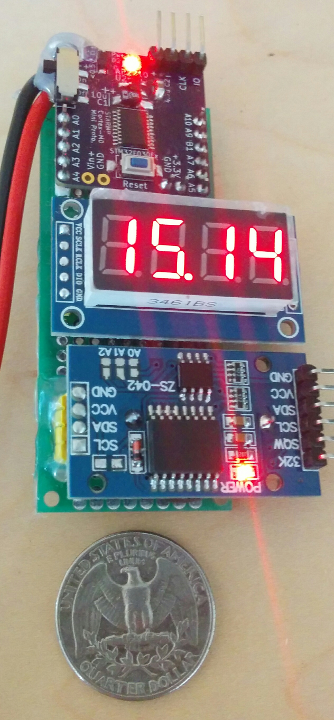
A li’l DS3231 clock at 3:14PM.


Phil
September 14, 2018 at 4:13 am
Thanks. Nice work. I’m trying to do the same and hope this will help if I get stuck!
swaroop
October 13, 2019 at 1:41 am
Nice Tutorial
Which Compiler are you using for this? Are you using Linux environment for this. Let me know.
Vivonomicon
October 15, 2019 at 2:14 pm
Thanks! This example project uses the ‘arm-none-eabi-gcc’ toolchain (GCC for bare-metal ARM platforms), and Make to automate the build process. If you’re familiar with Make, you can see how the individual commands fit together in the project’s Makefile on github:
https://github.com/WRansohoff/STM32x0_DS3231_I2C_Example/blob/master/Makefile
I also wrote a tutorial about getting started with bare-metal STM32 development, although I keep meaning to revise the first few of these guides with some things that I’ve learned since I wrote them:
https://vivonomicon.com/2018/04/02/bare-metal-stm32-programming-part-1-hello-arm/
venkat
January 21, 2020 at 9:32 am
Can we erase the AT24C32N? For that what we have to do? Is it byte wise erase or sector wise? Please confirm.
Thanks for the tutorial
Vivonomicon
February 11, 2020 at 3:33 pm
Well, you can find more information about the command set in the chip’s datasheet:
https://ww1.microchip.com/downloads/en/DeviceDoc/doc0336.pdf
I haven’t used it to store much data at once, so I’ve always just overwritten individual bytes with zeros. I’m not aware of a specific ‘mass erase’ command, but it looks like there is a ‘page write’ command which lets you send a stream of data to write an entire page at once; that might be a little bit faster.
Good luck – I’d be interested to hear if those chips do have an ‘erase everything’ command which you can find.
Aleksey
February 14, 2020 at 6:42 am
Good lesson. Do not want to do a lesson on connecting the RTC DS3231 + LCD1602 two displays or one to STM32 on CMSIS?
Vivonomicon
February 25, 2020 at 6:22 am
I haven’t used those small “character LCD” displays much, but good idea – they probably would work well with one of these RTC modules to make something like an alarm clock.