
In a previous entry in this tutorial series, I tried to walk through some basic steps for writing an example STM32 program which toggled an LED on and off when a button is pressed. But that program only checked the button’s status once every cycle of the ‘main’ loop, and in a complex application each loop iteration could take a fairly long time. If a button press were very short and our application was busy for a long time, the program could miss the input.
When you want to respond to input very quickly and consistently on a microcontroller, it is usually a good idea to use a ‘hardware interrupt’ to run some code when certain hardware events are detected. In this tutorial, we will look at the STM32’s ‘EXTI’ interrupt lines, which can be set to trigger when the state of a GPIO pin changes.
And once we have a simple ‘button press’ interrupt triggering, we can easily demonstrate a real-world use by extending it to listen for faster inputs such as “rotary encoder” dials:
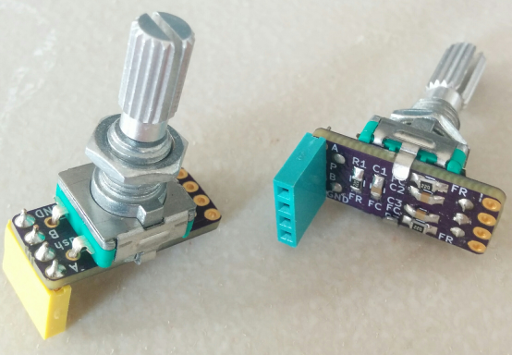
A couple of “rotary encoder” dials – the small resistors and capacitors on the back are for debouncing.
This type of dial ‘clicks’ in small steps when turned in either direction; they are nice tactile inputs, but it can be difficult to read them without hardware interrupts because of the large number of rapid pulses that they can generate when you twist them. So let’s get started!
What Do ‘EXTI’ and ‘NVIC’ Mean?
First, some background. We will use the ‘EXTI’ peripheral to trigger a hardware interrupt from a GPIO input pin. ‘EXTI’ stands for ‘EXTended Interrupt controller’, and its purpose is to extend the number of hardware interrupts available to us programmers. Basically, the chip’s “ARM Cortex-M0” core is where these interrupts originate from, and the people designing the STM32F0 chips cannot control how those ARM interrupts are structured. I think that ST buys the ‘core’ designs and builds around them – as do other manufacturers like TI, NXP, Cypress, etc – which would make sense considering the insane complexity of these systems.
The ARM ‘hardware interrupts’ peripheral included in the STM32F0 line of chips is described in Chapter 5 of the ARM Cortex-M0 technical reference manual, titled “Nested Vector Interrupt Controller”, but you don’t need to read all of that. I just linked to it as a reference, and to explain why this internal ARM peripheral’s acronym is ‘NVIC’. The C methods that we will use later for enabling an NVIC interrupt are included in the CMSIS device header files that we included in the last post.
So, the STM32 EXTI peripherals take a small number of NVIC interrupts and assign several different ‘extended interrupt events’ to each one. Remember the ‘Vector Table’ that we wrote earlier? As I understand it, that defines which code should be run for each NVIC interrupt. And since the EXTI interrupts represent only one of several possible events, our NVIC ‘interrupt handler’ function will need to check which EXTI event actually triggered the interrupt and act accordingly.
There are 32 EXTI lines on the STM32F0 line. The first 16 of them can be used to trigger hardware interrupts when changes are detected on any of the 16 GPIO pins associated with each GPIO bank. EXTI0 refers to pin #0, EXTI1 refers to pin #1, and so on. But the STM32 also has several different banks of GPIO pins (GPIOA, GPIOB, GPIOC, etc.), so there is a limitation that we can only use an interrupt for ‘Pin #X’ on one of those banks at a time. For example, we can have an interrupt on PA0 and PB1 at the same time, but not PA1 and PB1 since they have the same pin number.
You can see that in our STM32F031K6 vector table, there are only three NVIC interrupts dedicated to those 16 EXTI lines. EXTI0_1 can listen to pins 0 and 1, EXTI2_3 can listen to pins 2 and 3, and EXTI4_15 can listen to pins 4 through 15, inclusive.
Programming the Interrupt
Okay, that was a lot of text. To review, these chips have core “NVIC” interrupts which need to be enabled in addition to the actual STM32 peripheral interrupts that we want to use. Our code will configure the STM32’s “EXTI” line to listen on a specific GPIO pin, and then we will enable the NVIC interrupt. I’ll also go over writing a C method for the appropriate vector table entry.
And while I primarily discuss the STM32F031 chip in this post, all of the C code for enabling and using these EXTI interrupts should also work on an STM32L031 if the appropriate device headers and compiler options are used. This tutorial code will build on the previous examples in this series without describing each file in full, so here is a Github repository with a full example project if you want to review the basic structure, or if I do a poor job of explaining where different lines of code should go.
Configuring the EXTI Peripheral
It’s a good idea to set up the EXTI line to point to the correct GPIO pin (or signal) before actually turning the interrupt on. This is done with the ‘SYSCFG’ (System Configuration) peripheral, which we need to turn on using an RCC register, just like the GPIOB peripheral:
RCC->APB2ENR |= RCC_APB2ENR_SYSCFGEN;
The SYSCFG peripheral is in the ‘APB2’ clock domain, so we use the APB2ENR register to turn it on. To assign an EXTI line to a GPIO bank, we need to set four bits in one of four EXTICR registers. They are described in Section 9.1 of the STM32F0xx reference manual. 0x0 maps a line to GPIOA, 0x1 maps a line to GPIOB, and so on. Each pin uses four bits, so there are four contiguous registers for the 16 possible pins. The SYSCFG struct defined in the device header files treats them as a 4-element array of registers called EXTICR instead of using EXTICR1, EXTICR2, etc. We can set the correct values using the BUTTON_PIN macro that we defined last time in main.h:
// Set SYSCFG to connect the button EXTI line to GPIOB.
SYSCFG->EXTICR[(BUTTON_PIN/4)] &= ~(0xF << ((BUTTON_PIN % 4) * 4));
SYSCFG->EXTICR[(BUTTON_PIN/4)] |=  (0x1 << ((BUTTON_PIN % 4) * 4));
Or if you prefer, you can be a bit more clear by using the EXTICR macros defined in the device header files if you know what pin you want and don’t expect that to change – this would be for pin B1:
SYSCFG->EXTICR[0] &= ~(SYSCFG_EXTICR1_EXTI1_Msk);
SYSCFG->EXTICR[0] |=  (SYSCFG_EXTICR1_EXTI1_PB);
With EXTI line 1 mapped to GPIO port B, we can set what type of inputs we want to listen for. This only requires three registers. Setting a bit in EXTI->IMR enables the interrupt for that EXTI line, setting a bit in EXTI->RTSR configures an interrupt to trigger on a ‘rising edge’ transition from 0 to 1, and setting a bit in EXTI->FTSR configures an interrupt to trigger on a ‘falling edge’ transition from 1 to 0. These registers are described in section 11.3 of the STM32F0 reference manual.
With the button/dial/etc. connected to ground on one side and the pin configured with a pull-up resistor, we want to listen for a ‘falling edge’ to detect button presses. A ‘rising edge’ would indicate that the button was just released from a pressed state:
// Setup the button's EXTI line as an interrupt.
EXTI->IMR  |=  (1 << BUTTON_PIN);
// Disable the 'rising edge' trigger (button release).
EXTI->RTSR &= ~(1 << BUTTON_PIN);
// Enable the 'falling edge' trigger (button press).
EXTI->FTSR |=  (1 << BUTTON_PIN);
Enabling the NVIC Interrupt
To listen for a button on pin B1 like in our previous example, we’ll want to use the EXTI0_1 NVIC interrupt. Turning it on is simple – we call one command to define the interrupt’s priority, and one to actually enable it. In more advanced ARM cores, the NVIC interrupts have more complicated priority and sub-priority settings, but the ARM Cortex-M0 only has four basic levels. ‘Level 0’ is the highest priority, and ‘Level 3’ is the lowest. With only one interrupt active, it doesn’t really matter what priority we use, so I’ll go with 3:
// Enable the NVIC interrupt for EXTI0 and EXTI1 at minimum priority.
NVIC_SetPriority(EXTI0_1_IRQn, 0x03);
NVIC_EnableIRQ(EXTI0_1_IRQn);
Note that if you change your BUTTON_PIN value to something other than 0 or 1, you will also need to use a different NVIC interrupt. As I mentioned earlier, the EXTI0_1 interrupt only works for pins 0 and 1. For pins 2-3 you can use EXTI2_3, and for pins 4-15 you can use EXTI4_15.
Writing the Interrupt Handler
With the NVIC interrupt enabled and the EXTI line configured to listen on pin B1, the chip will now jump to whatever memory address is specified under the vector table’s EXTI0_1 entry when our button is pressed. Earlier in this series of tutorials, we pointed all of our vector table’s entries to a ‘default handler’ which was nothing but an infinite loop. Jumping to that ‘default handler’ is practically an error, because it means that we have enabled an interrupt without defining an interrupt handler for it to use.
To run a C function when the interrupt triggers, we just need to define one with the same name as the vector table entry. That will override the ‘default interrupt handler’ link, because we used the weak keyword when defining those defaults in the vector table. I used separate interrupts files for this method (nvic.c / nvic.h), and added a simple void function definition to the header file. Double-check your vector file and change the name if necessary:
void EXTI0_1_IRQ_handler(void);
When the interrupt triggers, the microcontroller will set a status bit in the EXTI_PR register to tell us which EXTI line was triggered. We can check that register to make sure that it was the button pin attached to EXTI1 which caused the interrupt, and then we need to clear the bit to allow new EXTI1 interrupts to trigger. Somewhat confusingly, we need to set the EXTI_PR status bit to 1 (not 0) to clear it. So this is our mildly strange interrupt handler for a push-button input; the led_on variable will be discussed in the next section:
void EXTI0_1_IRQ_handler(void) {
  if (EXTI->PR & (1 << BUTTON_PIN)) {
    // Clear the EXTI status flag.
    EXTI->PR |= (1 << BUTTON_PIN);
    // Toggle the global 'led on?' variable.
    led_on = !led_on;
  }
}
Updating the ‘main’ Files
As a final step, we should update our ‘main’ files. I created a new global.h file for defining includes and values which every file should have access to. It is included by every other header file in the project (in this case, main.h and nvic.h). I moved the device header file includes and the macro definitions like LED_PIN from main.h to global.h, and added an led_on variable:
volatile unsigned char led_on;
The volatile qualifier tells the compiler that the variable can change at any time. Sometimes the compiler will look at a block of code, decide that it will not change a variable’s value, and cut some corners using the assumption that the value will never change. But hardware interrupts can happen at more or less any time, so you should use the volatile keyword to tell the compiler not to assume anything about variables which hardware interrupts can modify.
Also, if you use this project structure of “global variables defined in a global header file”, you won’t be able to pre-initialize those variables unless they’re declared static – the compiler might complain about ‘multiple definitions’. But you can get around that by setting starting values at the beginning of your main method. If that annoys you, a cleaner option is to use the extern keyword to access variables across files, but I want to keep things simple for now.
No matter how you decide to define global variables in your project, the entire main loop can be nothing but setting the LED pin according to the led_on value:
// Light the button only if it should be on.
while (1) {
  if (led_on) {
    GPIOB->ODR |= (1 << LED_PIN);
  }
  else {
    GPIOB->ODR &= ~(1 << LED_PIN);
  }
}
You can also set the GPIOB->ODR register directly in the interrupt handler, in which case the main loop could be completely empty. I just didn’t want to talk about hardware interrupts without mentioning the volatile keyword, because ignoring that can lead to some frustrating bugs as you start to write more complex applications.
Results
At this point, you should be able to upload your program and see the same thing as the last tutorial; the on-board LED toggles on and off when the external button is pressed:
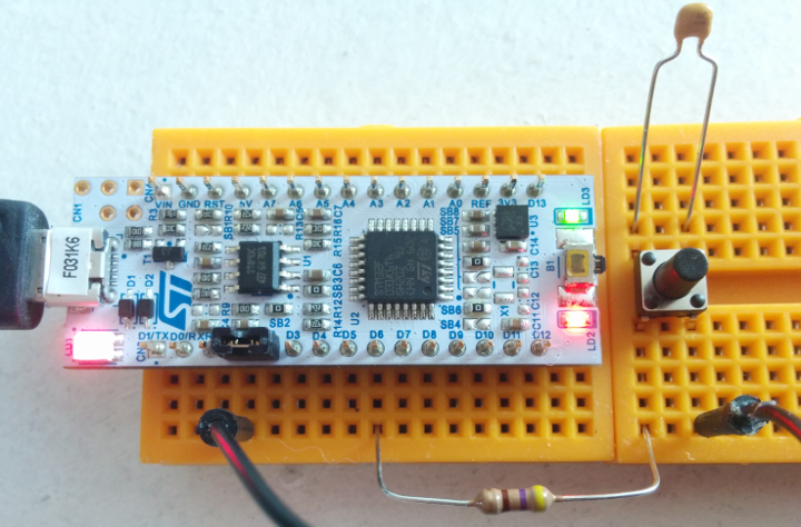
Same as before; the green LED connected to PB3 toggles on/off whenever the button is pushed down.
Don’t forget to #include "nvic.h" in main.h, and add nvic.c to your Makefile. I did forget those steps initially, and the compiler didn’t raise any warnings or errors because the EXTI0_1_IRQ_handler label was already weakly linked to the ‘default interrupt handler’ in our vector table. So the program compiled and uploaded, but nothing happened when I pressed the button because the chip jumped to the ‘default handler’ and stayed there. Compiling the project with the interrupt files fixed the problem, because the EXTI0_1_IRQ_handler definition in nvic.c was associated with the vector table label of the same name. In GDB, you can use the bt or backtrace command to view the chip’s current function stack and check where it is in your program.
Using ‘Rotary Encoders’
With a single push-button working, let’s move on to a “real world” use of GPIO hardware interrupts: a “rotary encoder” dial.
What is a Rotary Encoder Dial?
The term “Rotary Encoder” can refer to a lot of different things, as Wikipedia will tell you. I am specifically talking about the sort described as ‘Incremental Rotary Encoders’ on that page. They are simple devices which ‘click’ both clockwise and counter-clockwise in small steps, and they usually have two data pins labeled A and B. When they are ‘clicked’ in one direction, the A pin pulses just before the B pin. In the other direction, the B pin pulses just before the A pin.
It is difficult to listen for this sort of input in a simple loop, because the pulses happen extremely quickly. It’s easy to miss a ‘click’ in either direction, and you can also read the wrong direction if you miss the first pulse of a ‘click’ but catch the second one. With a hardware interrupt, however, the chip can reliably run our interrupt code on every pulse and listen very accurately.
Listening With a Hardware Interrupt
The concept behind the interrupt code is simple: with our microcontroller running at a speed in the range of megahertz, an interrupt on the first pulse should be able to finish running its interrupt handler code before the second pulse is triggered by the rotary encoder. So even if we only set an interrupt on one of the rotary encoder’s data pins, we can still determine the direction of the ‘click’ by checking the state of the other data pin at the very beginning of the interrupt handler. If the other pin is already high, then the interrupt pin got the second pulse. If it is still low, then the interrupt pin got the first pulse. Since the direction of a ‘click’ is indicated by which pin pulses first, that gives us our answer:
  if (GPIOB->IDR & (1 << ROTARY_PIN_B)) {
    led_on = 1;
  }
  else {
    led_on = 0;
  }
That interrupt handler code simple turns the LED on/off depending on the last direction that the dial was spun in, but you could also count a number up/down as an example.
Note that it is good practice to do as little work as possible in hardware interrupt handlers; they should finish as quickly as possible so the chip can get back to what it was doing, and so that other interrupts can be processed quickly. If you want an interrupt to trigger complicated or long-running logic, one way to do that is to simply mark a variable (like led_on) inside of the interrupt, and then check that variable’s status in your main loop to decide whether or not to run the lengthy task.
Updating ‘main’ and Results
The only remaining step is to define a macro for ROTARY_PIN_B in the global.h file, and set it up as a GPIO input pin with the pull-up enabled. (I continued using BUTTON_PIN instead of defining a new ROTARY_PIN_A so that I wouldn’t need to change the code much for these examples).
#define ROTARY_PIN_B (0)
On the STM32F031K6 ‘Nucleo’ board, PB0 is marked D3. We can use the same GPIO register settings as before, and we don’t have to set up another interrupt:
GPIOB->MODER &= ~(0x3 << (ROTARY_PIN_B*2));
GPIOB->PUPDR &= ~(0x3 << (ROTARY_PIN_B*2));
GPIOB->PUPDR |= (0x1 << (ROTARY_PIN_B*2));
It would have been nice to have a display count up and down as the dial is spun, but there is only one LED available on these ‘Nucleo-32’ boards and I want to keep things simple. So after uploading and running the project with this new interrupt handler, the onboard LED should turn on when the rotary encoder is spun in one direction, and off when it is spun in the other:
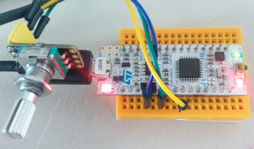
STM32 connected to a rotary encoder – twisting in one direction turns the LED on, the other turns it off.
Conclusions
As you can see, hardware interrupts are a good way to respond to external inputs very quickly. And beyond inputs like buttons and dials, many interrupts can also be configured to trigger on internal events, such as ‘timer’ peripherals which can have the chip perform actions on a schedule.
And again, here is a Github repository with an example project for the code described here.
I’m not sure what the next post will be about yet. I was thinking of looking at the hardware peripheral for a common communication protocol like I2C or SPI, but I might also look into using a ‘PWM’ peripheral to adjust the brightness of the onboard LED. Or, I might go over the single-wire interface used by individually-addressable colored LEDs such as the ever-popular WS2812B. Those are lots of fun in all kinds of random projects.


kratatau
September 26, 2019 at 10:09 am
Another excellent example. After a bit of tuning works nicely on my Nucleo F303. You have a good teaching skills 🙂 Thank You very much..
Vivonomicon
October 15, 2019 at 2:18 pm
Thank you! I’m glad to hear it works for you, congrats on porting it to a different board.
Don Burgess
December 14, 2019 at 8:46 am
Thank you for these educational posts.
To get the Rotary-Encoder circuit to work, I had to incorporate your “debouncing circuit”.
There is a small typo in your instructions: PB0 is marked D3 rather than D7.
Vivonomicon
February 11, 2020 at 3:48 pm
Oh, thank you for the correction!
Yeah, rotary encoders have much faster signals than buttons, but you might want to be ready to do some sort of debouncing wherever you use edge-triggered interrupts.
Sometimes people will do de-bouncing in software too, by checking the value a few times in a row right after it changes or waiting briefly to see if the signal switches again. But it can be a little bit tricky to do that while still keeping your interrupt handlers as short as possible.
Ahmet Erdem
March 28, 2020 at 2:51 pm
I love your blog posts, thank you very much for quality and clear content. I would like to make a request on this baremetal series because while I follow it I had some bugs and problems from time to time. I believe a post where you implement the ‘printf’ function from stdio.h and how to debug using GDB and breakpoints.
Because as a developer coming from the welcoming arms of an OS, it is quite challenging to get even simple runtime tools working on top of an embedded platform. I hope one day, you decide to make a post on this topic.
Thank you again!
Vivonomicon
April 14, 2020 at 11:42 am
Good idea, thank you for the suggestion! I have been planning a post about the STM32 UART peripheral, including how to implement ‘printf’ over UART, but between the outbreak and my ongoing move across the country, it might be a few months before I finish it.
Sorry, that probably should have been one of the first things that I wrote about, but hindsight is 20/20.
Hamish
August 2, 2020 at 12:34 pm
Hi,
Thanks for this (and the other) articles wrt the stm32 programming.
They are a great help (re)-introducing me to programming this micocontroller(-family).
Wrt using a rotary encoder, the f103 but also the F031 and L031) have circuitry onboard to directly read the encoder (using a general purpose timer, F031: timer 1,2,3, L031, 2,21,22, F103: timer 1 to 4). It takes care of all the housekeeping wrt to counting and filtering noise and just has a value present in a register.
Thanks again for putting stuff like this on the web, it’s been a great help.
Vivonomicon
August 2, 2020 at 9:41 pm
Thanks for the tip! I keep meaning to learn more about the timer peripherals’ advanced features; they are surprisingly intricate.
I was trying to demonstrate how interrupts can work where a busy loop might fail, but you’re right that ARM Cortex-M interrupts can still add a decent amount of overhead. Every time that an interrupt triggers, it takes at least a dozen clock cycles to actually enter the interrupt handler. Actions like saving/restoring the CPU registers eat precious time, so using a timer peripheral does sound like a more efficient approach for rotary encoders.
Thanks for pointing that out, and I’m glad that you found the post helpful.