
In a previous post, I wrote about designing a ‘breakout board’ for an SSD1331 OLED display with 96×64 pixels and 16 bits of color per pixel. With the hardware already put together, this post will cover writing a basic software driver for the displays. To keep things simple, we will talk to the display using software SPI functions instead of the STM32’s SPI hardware peripheral.
If you want to skip assembling your own boards, you can also buy a pre-made display such as this one sold by Adafruit. They have also written a library for these displays which works with several common types of microcontrollers, if you just want to use them without worrying about the display settings. But if you want to try understanding this sort of communication at a lower level, read on!
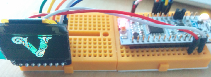
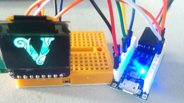
The finished program will display a predefined framebuffer, like this little logo!
Since many small microcontrollers – including the STM32F031K6 discussed in this example – don’t have 12KB of RAM available to store a 96×64 display at 16 bits per pixel, I’ll use a framebuffer with just 4 bits per pixel in this example (3KB), and map those 16 values to a palette. This example builds on the first few “Bare Metal STM32 Programming” tutorials that I’ve been writing, so here is a Github repository with the entire example project (including supporting files) if you don’t want to read those.
Background
SPI: ‘Serial Peripheral Interface’
These displays communicate using a standard called “SPI”. The good news for this tutorial is that it is a simple protocol to implement at its most basic level. Usually, an SPI bus has two data lines and a clock line shared between two circuits. Each data line has a ‘direction’ – one chip outputs to it, and the other listens. Every time that the clock line switches in one direction (low->high or high->low), each chip is supposed to write to its ‘Output’ line. And every time that the clock line switches in the other direction, each chip is supposed to read its ‘Input’ line. So one clock pulse sends one bit, and typically we send one byte at a time.
The SPI standard is sort of old, and it uses a bit of an unfortunate naming standard that lists the host circuit as ‘Master’ and listening circuits as ‘Slave’. MOSI stands for ‘Master Output, Slave Input’ and MISO stands for ‘Master Input, Slave Output’. I tend to prefer classifiers like the ‘Host’ / ‘Device’ used by newer standards like USB, but the decades of accumulated documentation and acronyms won’t easily accommodate that with standards like SPI.
Anyways, there is also usually a CS pin which stands for ‘Chip Select’. If it is 0, the device will listen to data sent on the SCK and MOSI lines. If it is 1, the device will ignore them. These pins let your microcontroller communicate with different SPI devices on the same SCK/MOSI/MISO lines by only pulling one CS pin to 0 at a time.
The SPI standard also supports plenty of other features for doing fancy things like verifying that the data received matches the data sent, but for talking to these displays, we only need to use the most basic interface on the clock line and one of the data lines. The SSD1331 doesn’t even seem to have an ‘Output’ SPI pin, so we can ignore the MISO line. Just think like a politician.
This means that a method for writing a byte of data over SPI is very simple – loop through 8 cycles of pulling the clock pin low, setting the data pin to the current bit’s value, and pulling the clock pin high again:
/*
 * Write a byte of data using software SPI. For each bit:
 * 1. Pull the clock pin low.
 * 2. Set the 'MOSI' data pin to the correct value.
 * 3. Pull the clock pin high.
 */
inline void sspi_w(uint8_t dat) {
  uint8_t sspi_i;
  // Send 8 bits, with the MSB first.
  for (sspi_i = 0x80; sspi_i != 0x00; sspi_i >>= 1) {
    GPIOB->ODR &= ~(1 << PB_SCK);
    if (dat & sspi_i) {
      GPIOB->ODR |=  (1 << PB_MOSI);
    }
    else {
      GPIOB->ODR &= ~(1 << PB_MOSI);
    }
    GPIOB->ODR |=  (1 << PB_SCK);
  }
}
I used the function name sspi_w, short for ‘software SPI write’, and the pin definitions like PB_SCK are in main.h. Note that while we send the ‘Most Significant’ (left-most) bit first and set the data pin while the clock pin is low, different devices might expect different settings. The settings for these displays are described in Section 7.1.3 of the SSD1331 datasheet, titled ‘Serial Interface’.
The inline qualifier asks the compiler to copy the entire method into the program every time that we call it, instead of performing a function call. That can increase the size of the program, but it should also make the method run faster because the microcontroller won’t have to push and pop a stack frame. You can find more information here.
What Exactly is an ‘SSD1331’?
Technically the part number, SSD1331 refers to a little tiny ‘driver chip’ between the ribbon connector and the actual screen; I think that you can see it as a small silver rectangle right between the rear of the display panel and the ribbon connector. It listens for communications from our microcontroller, and takes care of actually setting the color, brightness, and contrast of each pixel. It also has enough RAM to remember each pixel so that the display can refresh without continued input from us.
To turn on the display and start drawing to it, we need to send some startup commands to the “driver chip” to tell it how we want it to draw to the screen. These commands are listed in Sections 8 and 9 of the datasheet. Happily, this datasheet provides fairly clear descriptions of each command, which seems pretty rare among displays and screens. The basic procedure will be to issue a ‘Display Off’ command, send the initialization commands, and then issue a ‘Display On’ command. Once that is done, we can simply send pixel data to the display one byte at a time. With the device initialized to address the entire display, it will automatically reset to position (0,0) after (96 * 64) = 6,144 pixels are drawn. Each pixel is 16 bits of data – 5 red, 6 green, and 5 blue.
The “4-wire SPI” protocol which we will use is similar to the very basic SCK/MOSI/CS one described above, but with the addition of a DC (“Data or Command?”) pin. When the DC pin is 0, the display treats data we send it as a command. When it is 1, the screen treats data we send as pixel colors to draw. So, we should also add a function for sending commands to the display:
inline void sspi_cmd(uint8_t cdat) {
  // Pull the 'D/C' pin low, write data, pull 'D/C' high.
  GPIOB->ODR &= ~(1 << PB_DC);
  sspi_w(cdat);
  GPIOB->ODR |=  (1 << PB_DC);
}
The Display Code
Initialization Commands
As mentioned above, these commands are all listed and explained in Section 8 of the SSD1331 datasheet. It seems like you can mostly use the default ‘reset’ values, with a handful of exceptions described below. But I’ll still try to explain my current understanding of each command in a simple startup sequence.
Many of these commands have a number of ‘option bytes’ which should be sent after the ‘command byte’. These options should be sent to the driver as commands, not display data. That means that the sspi_cmd method should be used for all of these initialization commands, including their options.
0x15: ‘Set Column Address’
This command sets the horizontal range of pixels which we want to address. You can draw to any rectangular area of the screen, but these values reset to cover the entire display width of columns 0-95. It is followed by two option bytes, representing the start and end column respectively.
0x75: ‘Set Row Address’
Similar to the previous command, this sets the vertical range of pixels to address. The default is the entire display height of rows 0-63, and it also expects two option bytes for the start/end rows.
0x81, 0x82, 0x83: ‘Set Contrast [A, B, C]’
These commands set contrast values for the A (0x81), B (0x82), and C (0x83) colors. Depending on the color mode we select, A/B/C can represent different primary colors – in this example A will be Red, B will be Green, and C will be Blue. Each contrast value resets to 128, or approximately 50%.
These commands each expect one option byte, with the new contrast value for the appropriate color. I’m no color guru, but the ‘green’ colors look very strong at the default values; I used 0x60 instead for color B. But play around and see what you like!
0x87: ‘Master Current Control’ (‘Set Brightness’)
This command sets the maximum current which will be allowed to flow through each pixel. More current means more brightness. This command expects one option byte, with the new brightness value. The default value is the maximum of 0x15, which multiplies the IREF value by 16. A value of 0x00 multiplies it by 1. If you read my post about designing boards for these displays, this is what the IREF resistor was for. The resistor sets a ‘reference current’ with the equation:
(VCC - 3) / IREF
With a VCC voltage of 12V, this means that we have an IREF of 7.5uA with a 1.2MΩ resistor, or the recommended value of 10uA with a 900KΩ resistor. Those values correspond to a maximum current of 120uA and 160uA, respectively. Changing other settings, such as the ‘Contrast’ commands, can further reduce current consumption. I believe that these values are per-‘segment’, with each ‘segment’ representing a single column for a single color. If that were the case, there would be 3 ‘segments’ per pixel column, and we can probably expect a maximum current consumption of about 50mA at 12V, with the entire display fully on at its maximum brightness and contrast:
((3 * 96) * 160) / 1000 = 46.08
0x8A, 0x8B, 0x8C: ‘Set Second [A, B, C] Pre-Charge Speed’
These commands set how quickly each color’s “Precharge 2” step should run. The display uses a handful of “precharge” steps to set each pixel’s color, but I don’t quite understand how they work. If you are curious, you can learn a bit more in this reference document or in section 7.7 of the SSD1331 datasheet, but I think that these values basically just define how quickly the driver will try to set each pixel’s color.
They expect one option byte with the new ‘scaling factor’, and they default to the A/B/C color contrast values, which the datasheet indicates should be a safe starting point. Adjusting this setting may allow the display to be driven at higher speeds or more power-efficiently, but it looks like it can also lead to inconsistent or flickering pixel colors.
0xA0: ‘Set Remap and Display Settings’
This command only expects one option byte, but it is split into several bits which work together to define how the display should handle pixel data. There are options for flipping the display, setting the color depth and A/B/C color definitions, which direction to ‘move’ when progressing to the next pixel, and so on.
The individual bits are described in Section 9.1.6 of the SSD1331 datasheet, but I will use an option value of 0x60 to use ’16-bit color format 1′ and avoid drawing the rows in an ‘odd then even’ order. Once you have an image drawing to the display, try playing around with this value to get a feel for how each option changes the image’s orientation.
0xA1: ‘Set Display Start Row’
Set the row to start drawing at. Expects one option byte, which contains the row to start drawing at. Defaults to 0, with a valid range of 0-63.
0xA2: ‘Set Display Offset’
Set the horizontal ‘column’ offset to start drawing at. Combined with the row offset, this defines a starting coordinate for pixel data which is sent to the display. And just like the row offset, this command expects one option byte containing the horizontal column offset in pixels, and defaults to 0.
0xA4, 0xA5, 0xA6, 0xA7: ‘Set Display Mode’
These four commands each set a different ‘display mode’. 0xA4 turns the display on normally, and 0xA7 inverts the display colors. 0xA5 turns all of the display’s pixels on regardless of pixel data, and 0xA6 turns them all off. I think that 0xA5 and 0xA6 are intended for testing. None of these commands expect any option bytes.
0xA8: ‘Set Multiplex Ratio’
This sets the ‘mux ratio’, from 15 to 63. I think that it defines how many rows can actually be addressed, and setting a lower value would disable pixel rows towards the ‘bottom’ of the display. It accepts one option byte with the new multiplexing value, but I haven’t tried changing it from the default value of 63 (‘enable all rows’) yet.
0xAB: ‘Dim Mode Setting’
I haven’t used this command, but I think that it sets separate contrast values for the A/B/C colors and a single precharge setting used by the display’s energy-saving ‘dim mode’. It accepts 4 option bytes; one for each color’s contrast value, and one for the precharge value.
0xAD: ‘Set Master Voltage Source’
This command accepts one option byte, which sets the display’s voltage source. Many similar drivers have built-in charge pumps to generate higher bias voltages for the display, but the SSD1331 does not. So there is only one valid value for this command, and it is 0x8E which uses VCC as the core voltage supply.
The reset value is 0x8F, which is invalid, so this setting must be changed before turning the display on.
0xAC, 0xAE, 0xAF: ‘Set Display On/Off’
These commands set the display’s on/off status. 0xAE turns the display off, 0xAF turns it on, and 0xAC turns it on in ‘dim’ mode. None of these commands expect any option bytes.
0xB0: ‘Set Power Save On/Off’
This command sets power save mode on or off. It accepts one option byte, which contains the new setting. If the option byte is 0x1A, power save mode is enabled. If it is 0x0B, power save mode is disabled. The default is 0x1A, enabled.
0xB1: ‘Adjust Precharge Phase 1/2’
This command adjusts the amount of time spent in the first two ‘precharge’ stages. It accepts one option byte; bits 7-4 set the number of ‘display clock’ cycles for phase 1, and bits 3-0 set the number of cycles for phase 2. The default is 0x74 – 7 cycles for phase 2 and 4 cycles for phase 1.
0xB3: ‘Set Display Clock Divider and Oscillator Frequency’
This command sets the chip’s oscillator frequency, and how much to divide that frequency by for the ‘display clock’ signal. It accepts one option byte; bits 7-4 set the oscillator frequency according to the graph in section 9.1.16 of the SSD1331 datasheet, and bits 3-0 set the ‘display clock’ division factor (0x0-0xF = 1-16). The default value is 0xD0.
0xB8: ‘Set Gray Scale Table’
I didn’t use this command, because it expects 32 option bytes. As I understand it, they let you set a ‘gamma curve’. Each byte sets the PWM pulse width for a certain ‘brightness’ value. It defaults to a linear scale; for example, a brightness of 4 turns the LED ‘on’ for 4 times longer than a brightness of 1. But you can adjust it to your liking.
0xB9: ‘Reset the Gray Scale Table’
This command resets the display’s gamma curve to the default linear setting. It is what I will use instead of 0xB8.
0xBB: ‘Set Precharge Level’
This command sets the precharge voltage level. As I understand it, the precharge ‘on’ step is split into two major parts – “voltage drive” and “current drive”. I think that the former tries to charge the pixel’s capacitor to a certain voltage before a higher-current power source is applied to drive the desired color’s ‘on’ brightness.
If I’m reading things right, that first “voltage drive” step can bring the capacitor’s voltage from anywhere to 0.1 * VCC through 0.5 * VCC. A single option byte determines the precharge level, and it defaults to 0x3E, or 0.5 * VCC.
0xBC, 0xBD, 0xE3: ‘NOP’
These commands are ‘no-op’ commands. The datasheet says they do nothing, so I won’t be using them.
0xBE: ‘Set VCOMH’
This command accepts one option byte, which sets ‘COM deselect voltage level’. I think that that means the voltage level below which some bits will be read as 0, and above which they will be read as 1. But I haven’t read much into this command. It can define a number of values between 0.44 * VCC and 0.83 * VCC. I will use the default value of 0x3E, or 0.83 * VCC.
0xFD: ‘Lock/Unlock Display’
This command can lock or unlock the display. When ‘locked’, the display ignores any commands and pixel data sent to it (except for the 0xFD command). When ‘unlocked’, it behaves normally. This command expects a single option byte; 0x12 will unlock the display, and 0x16 will lock it. It defaults to 0x12 so that the display resets to an unlocked state.
Initialization Sequence
So given all of those command definitions, you can basically just run them one-by-one in between “Display Off” and “Display On” commands. If you run into problems, you can check the initialization sequence that I used in the Github repository’s util.c file.
The Framebuffer
If you haven’t heard the term before, a ‘framebuffer’ is simply a block of memory used by a computer to store the current image to draw to a display. When the computer refreshes the display, it usually just starts at the beginning of its framebuffer and sends that data byte-by-byte. The SSD1331 driver chips have their own framebuffer, so we can just draw shapes and pixels without storing the whole screen in our microcontroller’s memory. But that approach is significantly less flexible, and it still winds up taking a lot of program space for complex non-repeating patterns.
On the other hand, high-resolution color displays require a lot of memory to store a whole framebuffer. Like I mentioned earlier, even these small screen take a decent chunk of space – if we stored a full 16 bits of color per pixel on a display with 96 columns and 64 rows, that would require 12KB:
(((16/8) * 96 * 64) / 1024) = 12
And the STM32F031K6 which I am using in this example is a humble chip, with only 4KB of RAM. We could still fit a framebuffer in its 32KB of read-only Flash memory if we only wanted to draw a static logo, but I wanted something more general-purpose for this example (spoiler alert, Tetris is on the horizon) so I used a 16-color palette which only requires 4 bits per pixel. That only comes out to 3KB:
(((4/8) * 96 * 64) / 1024) = 3
4 bits is also the size of a single hex digit, which is sort of convenient. To do that, we can define an array of ‘palette colors’ alongside the raw framebuffer memory in main.h:
// OLED logo colors.
#define OLED_BLK (0x0000)
#define OLED_LGRN (0x8628)
#define OLED_MGRN (0x5488)
#define OLED_DGRN (0x2E47)
// Color palette.
static uint16_t oled_colors[16] = {
  OLED_BLK, OLED_LGRN, OLED_MGRN, OLED_DGRN,
  0x0000, 0x0000, 0x0000, 0x0000,
  0x0000, 0x0000, 0x0000, 0x0000,
  0x0000, 0x0000, 0x0000, 0x0000
};
// To fit in 4KB of SRAM, use 4 bits per pixel, to
// map to up to 16 colors defined above. So, 2px per byte.
#define OLED_BUF_SIZE ((96 * 64) / 2)
// Default to a 'V' logo.
static uint8_t oled_buffer[OLED_BUF_SIZE] = {
  // (... 3,072 bytes ...)
};
You can refer to the Github repository’s main.h file for the logo I used, write/export your own, or just populate it with 0s and draw some shapes. There are also 12 colors leftover in the palette, since I only used black and three shades of green.
Drawing the Pixels
Once the initialization commands have been sent to the screen, we can start sending pixel data. With the settings I described above (and which you can look over in the example repository), the display will start drawing in the one corner of the screen. We just send pixel colors one by one, using the sspi_w method described earlier with the DC pin pulled high.
Every two bytes that we send will represent one pixel; the format is 5 bits of red color, 6 bits of green color, and 5 bits of blue color. Once the display receives a pixel color, it will set the current pixel’s color and move one pixel to the right. When the ‘cursor’ reaches the end of a row, it will move to the next row at column 0.
So basically, every 96 * 64 * 2 = 12,228 bytes (12KB) that we send to the screen rewrites the whole display, as long as the ‘set row/column’ commands are set to cover rows 0-63 and columns 0-95. Once the ‘cursor’ reaches the end of the last pixel, it will automatically jump back to the starting position, and we can start drawing again without issuing any new commands.
Here is a simple ‘main draw loop’ for decoding our framebuffer:
  uint16_t px_i = 0;
  uint8_t px_col = 0;
  uint16_t px_val = 0;
  while (1) {
    // Draw the buffer. (Each byte has two 4-bit pixels.)
    for (px_i = 0; px_i < OLED_BUF_SIZE; ++px_i) {
      px_col = oled_buffer[px_i] >> 4;
      px_val = oled_colors[px_col];
      sspi_w(px_val >> 8);
      sspi_w(px_val & 0x00FF);
      px_col = oled_buffer[px_i] & 0x0F;
      px_val = oled_colors[px_col];
      sspi_w(px_val >> 8);
      sspi_w(px_val & 0x00FF);
    }
  }
Conclusions
Well, that’s the basics of drawing to an SSD1331 display. We also got a one-way software SPI driver working, which is good for testing these displays on other chips with only slight modifications. For example, here is an 8-bit STM8S103F3 board that costs less than $0.75 drawing the same logo from its read-only flash memory (since it only has 1KB of RAM):
An STM8S103F3 drawing the logo from read-only memory.
So that’s fun. Here is a great tutorial on programming those cheap STM8S boards if you’re interested, but as the author notes they aren’t really that much cheaper than a generic STM32 board. I might write another post like this for an SSD1306 monochrome screen, although I want to work out how to support multiple sizes of those displays first. And I’d also like to write about listening to various types of sensors, so we’ll see what happens.


Ron Cromberge
October 20, 2018 at 4:22 am
Hello,
I’m stuck. Copied the code from GitHub. converted it to run in eclipse. But whatever I do I keep getting the same errors!
src/sspi.h:23:13: warning: inline function ‘sspi_cmd’ declared but never defined
inline void sspi_cmd(uint8_t cdat);
^~~~~~~~
src/sspi.h:21:13: warning: inline function ‘sspi_w’ declared but never defined
inline void sspi_w(uint8_t dat);
and of course several :
/Users/roncromberge/Desktop/STM32_Code/STM32F0_SSD1331_softSPI-master/src/main.c:80: undefined reference to `sspi_w’
/Users/roncromberge/Desktop/STM32_Code/STM32F0_SSD1331_softSPI-master/src/util.c:22: undefined reference to `sspi_cmd’
at first I thought I did something wrong in the conversion from your source to the eclipse project.
But now I tried to build the code direct from you’re makefile. And get the same errors.
So what is going wrong?
I tried it on a big Nucleo (stm32L476RG) with all the port conversions. And with the small Nucleo stm32L031K6
Greetings from Holland,
Ron
Vivonomicon
November 12, 2018 at 9:57 am
Hi, sorry to hear you’re having trouble – I haven’t tried using Eclipse as an IDE for these projects, but that warning looks like the `sspi.c` source file may not be getting included in the build step. I’m not exactly sure how the ‘System Workbench for STM32’ Eclipse port handles project builds, but could you check that all 3 source files are getting compiled and linked?
The `sspi_w` and `sspi_cmd` methods are only declared in the header file, but they should be defined in the source file.
Does that make sense? Sorry, I’ve been using GCC/Make for these tutorials because modern versions of Eclipse aren’t built for ARM processors, and I’ve been trying to write tutorials that work on cheap and portable platforms like Raspberry Pis and Chromebooks. Let me know if you have any suggestions for making things more clear.