
In a previous post, I walked through creating a basic project for an ‘STM32F031K6’ microcontroller to boot the chip into a ‘main’ C method. But the actual program didn’t do much, so in this post we will learn how to use the STM32’s ‘GPIO’ peripheral to listen for a button press and blink an LED.
The ‘Nucleo’ boards provided by ST have an LED already built into the board, but they don’t have a button (besides the reset one,) so we’ll need to connect one externally:
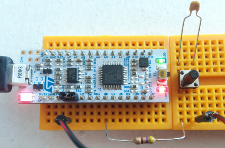
‘Nucleo’ STM32F031K6 board with a button.
The green ‘LD3’ LED is attached to pin B3 on the board. The 100nF capacitor across the button should help reduce noise, one side of the button connects to ground through a jumper wire, and I put a 470Ω resistor between the other side of the button and pin B1.
Strangely, the B1 pin is labeled ‘D6’ on the Nucleo boards; I think that ST wanted to use the same footprint and labeling as the popular Arduino Nano. You can find the actual pin mappings in section 6.11 of this reference document, or they’re also printed on the informational card that comes with the board. The resistor and capacitor are both optional – they’re just a very simple form of debouncing. Next up, the code!
Device Header Files
The STM32 chips have a lot of functionality which is not easy to represent in the standard C language. It has a number of hardware “Peripherals” to make it easier for you write programs which interact with the real world. They can do things like speak common communication protocols with other chips, run actions on timers, and send general-purpose signals to the pins connected to the chip.
The way that we read and program these peripherals is to check and set certain values at specific memory addresses. For example, in this tutorial we will set a bit to 1 in an “Output Data Register” to pull a pin’s voltage high enough to turn on an LED, and reset the same bit to 0 to pull the pin to ground and turn the LED off.
The companies which make these chips – ST Microelectronics in this case – usually also provide free header files which have definitions for which memory addresses go to which peripherals, and which bits do what. The bad news is, the definitions are all written as confusing acronyms, so it’s helpful to have your chip’s reference manual handy to check what the jumbles of letters mean. These supporting files are all located in the device_headers directory in the repository that I’ll link to at the end of this post.
Some of the device header files – like cmsis_gcc.h and the ones starting with core_cm – are “CMSIS” files which provide some common ARM Cortex-M definitions and things like software helpers for things like setting up hardware interrupts.
The stm32f0xx.h file provides general definitions shared across the entire STM32F0 line of chips, and the stm32f031x6.h file has the definitions specific to our STM32F031K6 chip. The system_stm32f0xx.h file is included by ST’s files because it is used in most of their auto-generated code, but its typical contents are not relevant to our low-level project. I included it as an empty file because the standard stm32f031x6.h file depends on it.
Now that we have external files to include, it makes sense to define a main.h header file for those sorts of definitions:
#ifndef _VVC_MAIN_H
#define _VVC_MAIN_H

#include <stdint.h>
#include "stm32f031x6.h"

// Define GPIOB pin mappings for our LED and button.
#define BUTTON_PIN (1)
#define LED_PIN    (3)

#endif
The #ifndef/#define/#endif statements are a common pattern in C programming; they prevent the file from being included more than once. If it hasn’t been processed yet, the #ifndef (‘if not defined’) will evaluate true and the file will be defined and included. If it has already been defined and included, then the #ifndef will return false and the file will be ignored.
The stdint.h header defines standard integer types like uint32_t, and the stm32f031x6.h file is the device header file discussed above. After the includes, we can define which GPIOB pins will be used for the button and LED. Pin B3 is connected to the on-board LED on ST’s “Nucleo” boards.
GPIO – General-Purpose Input/Output
With ST’s device files included, we can reference peripheral registers by name instead of address in our ‘main.c’ file. Before we use the GPIOB peripheral, we need to tell the chip to turn it on. By default, power is not applied to most of the chip’s peripherals for energy efficiency, so we need to turn them on by setting the appropriate bit in the RCC “clock enable” registers. For GPIOB, that looks like this:
// Enable the GPIOB peripheral in 'RCC_AHBENR'.
RCC->AHBENR |= RCC_AHBENR_GPIOBEN;
Those peripheral names are defined in the stm32f031x6.h file that we included earlier, and this line must be included early in the main method. If try to use a peripheral without first enabling its ‘clock’ in the RCC registers, it will not work, and the GPIO pins are no exception. If we wanted to use a pin in the GPIOA bank, we would also need to set the RCC_AHBENR_GPIOAEN bit.
With the peripheral initialized, we need to set up each individual pin – they default to ‘input mode’ with no pull-up/down resistors. There are four different registers which work together to set pin functions – they are described in section 8 of the reference manual, but here are the basics for each one:
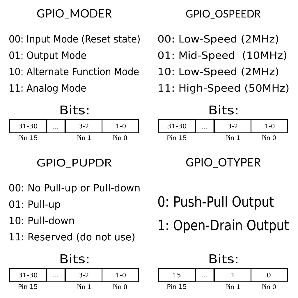
STM32 GPIO Pin Settings
The GPIO_OSPEEDR and GPIO_OTYPER settings are only used when the pin is set to ‘Output’ mode in GPIO_MODER. The ‘O’ in those register names stands for ‘Output’. The reset values are usually all zeros for those registers, with the exception of some debugging pins like A13 and A14.
GPIO Pin Initialization and Usage
For our ‘button’ pin, we want input mode with the pull-up resistor enabled – ‘Pull-Up’ means that the pin is “pulled” towards a ‘1’ / ‘High’ value. It will only read ‘0’ if the pin is connected to ground externally. STM32 chips have internal pull-up and pull-down resistors, but only one can be activated per pin. I think that they are close to 47KΩ each.
For the LED pin, we want a ‘push-pull’ output without any ‘pull-up/down’ resistors. ‘Push-pull’ outputs can pull a pin to either ‘1’ or ‘0’ while ‘open-drain’ outputs can only pull the pin to ‘0’. Open-drain outputs are useful if you have multiple devices set to ‘output’ on the same wire, because it prevents different devices from trying to pull the signal in two different directions at once and damaging each other. But we want push-pull, for simply turning an LED on or off:
// Initialize the GPIOB pins.
// B1 should be set to 'input' mode with pull-up.
GPIOB->MODER  &= ~(0x3 << (BUTTON_PIN*2));
GPIOB->PUPDR  &= ~(0x3 << (BUTTON_PIN*2));
GPIOB->PUPDR  |=  (0x1 << (BUTTON_PIN*2));
// B3 is connected to an LED on the 'Nucleo' board.
//    It should be set to push-pull low-speed output.
GPIOB->MODER  &= ~(0x3 << (LED_PIN*2));
GPIOB->MODER  |=  (0x1 << (LED_PIN*2));
GPIOB->OTYPER &= ~(1 << LED_PIN);
Strictly speaking, the register &= ~(value) statements are not necessary here; the chip will automatically set each register to 0 after a system reset. But when an option has more than one bit, it is good practice to reset the whole option before setting the bits you want. For example, if you had previously set a value to 01 and you tried to set its first two bits to 10 with the single command, register |= 0b10, then the value would actually get set to (01 | 10) = 11, which is not what you wanted. Clearing those two bits first with a command like register &= ~(0b11) prevents that problem without overwriting any other settings in the register.
Anyways, the button and LED pins are now initialized; we can check the current status of each GPIOB pin by reading the GPIOB peripheral’s ‘IDR’ (‘Input Data Register’) value:
uint32_t gpiob_input = GPIOB->IDR;
Bits 0-15 in that variable will be set to ‘1’ if the corresponding pin is currently at ‘logic high’ voltage and ‘0’ if it is at ‘logic low’ (ground). The first bit (0x1) is pin 0, the next bit (0x2) is pin 1, and so on; pin 15’s status is at position 0x00008000. The ‘ODR’ (‘Output Data Register’) works the same way, but we can also write to it to set pins’ states if they have been set to an output mode. For example, this will pull the LED pin high, turning the board’s LED on:
GPIOB->ODR |= (1 << LED_PIN);
The rest of this test ‘main’ program is just some simple logic to listen for a button press. We can’t just toggle the LED whenever the button is down, because even a very quick button press will span a lot of loop cycles. So we keep track of a ‘button_down’ variable to only toggle the LED when the button is pressed down from a previous ‘up’ state:
// Keep track of whether the button is pressed.
uint8_t button_down = 0;
while (1) {
  // Invert the IDR register since '0' means 'pressed'.
  uint32_t idr_val = ~GPIOB->IDR;
  if (idr_val & (1 << BUTTON_PIN)) {
    // The button is pressed; if it was not already
    // pressed, change the LED state.
    if (!button_down) {
      GPIOB->ODR ^= (1 << LED_PIN);
    }
    button_down = 1;
  }
  else {
    button_down = 0;
  }
}
And that’s all there is to it; you should be able to compile and upload that main method using our ‘minimal C’ project from the last post as an outline, and see that the green LED on the board changes state when pin B1 is pulled to ground through the button.
Also, now that we don’t need to inspect memory values in a debugger to see that the program is working, you can upload the code more quickly using the st-flash utility:
st-flash write main.bin 0x08000000
Conclusions
I hope that was fairly quick and digestible – especially compared to the last post! Using both our existing ‘minimal C program’ and ST’s handy pre-written register macros, we’re able to work with these chips and their peripherals in a way that is much less intimidating and time-consuming than raw assembly code. And of course, we can finally see that our code is working by looking at the LED.
So while the first two posts in this series covered a lot of ground very quickly while also assuming that you have some prior knowledge about programming and debugging, you really don’t need to understand all of that low-level supporting code to create a robust embedded application these days, and I hope that the concepts presented in this project are starting to feel a bit more familiar and accessible. As usual, corrections or suggestions for presenting things more clearly are very welcome.
Here is a repository with the code presented in this post.
The next post will probably cover how to use hardware interrupts – we’ll build on this understanding of GPIO pins to learn how to trigger an interrupt when a button is pressed. We’ll also cover the use of the ‘volatile’ keyword in embedded C, and learn a bit about ‘rotary encoder’ dials to demonstrate how it can be useful to respond to input signals the instant they happen, instead of checking the input state once every “loop” like we did in this example.


Jack CORNIL
April 1, 2019 at 6:16 am
Great Job !
I was desperately searching explanation on how to begin in pure C with STM32 until I found this blog.
You saved me
Thank you very much from France.
Bhavesh
November 10, 2019 at 12:21 am
Same as what Jack said.
Thanks from India!
Vivonomicon
December 4, 2019 at 6:28 am
Thanks, I’m glad that this helped both of you – good luck with your projects!
Emmanuel Buckshi
May 4, 2020 at 1:32 pm
Great blog! Useful reference for getting things up and running after switching to STM32. Thanks a lot!!
Vivonomicon
June 6, 2020 at 12:20 pm
Thanks, I’m glad it was helpful!
JAVID FARHAN
August 22, 2020 at 9:25 pm
This was very helpful, thanks a lot !
I use a blue pill, but I got a lot of ideas from this tutorial .
cheers from India !
Vivonomicon
September 6, 2020 at 2:54 pm
Glad you found it helpful, good luck with your future projects!