
Previously, I posted a tutorial about writing SVG files by hand to create simple patterns for a laser cutter to produce. But as I noted at the end of that post, writing that sort of file by hand is not a great solution. It is difficult to make a design that can be modified later, since SVG files don’t appear to have a good way to store variables yet.
So in this tutorial, I’ll go over the process of writing a simple Python script to create the same sort of “divided grid box” as in the previous SVG-writing tutorial across a wide range of dimensions. Then I’ll demonstrate how to use it to create a small 4-cell AAA battery holder out of something that isn’t plastic:
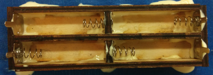
AAA battery case made of laser-cut wood
While “3D printing” a case allows you to add curves and small overhangs to hold the batteries in place, these simple laser-cut boxes can only have perpendicular edges. But I’ve found that using the sorts of spring contacts that you find in most commercial battery cases provides enough pressure to hold the batteries in place, at least until you hold the case upside down and knock it against something to pop them out.
Plus, 3D printing is comparatively slow; a battery case of this size would take between 30-60 minutes to print out on a Prusa i3 running at high speed, but a CO2 laser can cut out these parts in about 60 seconds. You do need to glue the pieces together, but if you adjusted the scripts to account for the “kerf” of your particular laser/material, you might be able to make them press-fit. Anyways, let’s get started!
Box Pattern Overview
This script will design boxes using the same approach described in the previous “writing SVG files” tutorial. But to make things easier on the user, it will produce a single pattern file with the correct number of each type of part placed appropriately:
- One ‘base’ for the box. Each of the ‘wall’ parts will fit into the base perpendicularly, like puzzle pieces.
- Two ‘vertical edge walls’, which spans the box’s entire length.
- At least two ‘horizontal wall/dividers’ which span the box’s entire width, minus the width of the material taken up by the two ‘vertical edge walls’. This will also double as a ‘divider’ to separate ‘rows’ of grid cells within the box.
- Any extra ‘vertical dividers’, which only span the height of a single grid cell to separate ‘columns’ between horizontal dividers.
If you’re okay with ignoring the laser’s kerf, we can make the edge wall dividers share edges with the box base in order to save material. Here’s what the generated pattern will look like, with each part labeled:
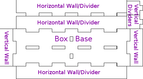
2×2 AAA battery box generated pattern
Finding Dimensions
Checking Parameters
The first thing our script will need to do is define the dimensions of the box that it will produce. I decided to accept the following parameters in this simple example script. For simplicity, I will assume that dimensions are specified in millimeters:
- Interior “width” (X-axis) of a grid cell.
- Interior “length” (Y-axis) of a grid cell.
- Depth (Z-axis) of each grid cell.
- Number of “horizontal” (X-axis) grid cells.
- Number of “vertical” (Y-axis) grid cells.
- Thickness of the material being cut.
That is all the information that we need to generate these patterns. There are better ways to handle arguments than this, but this is not a tutorial about command-line parsing, so I’m just going to grab the raw values passed in to the script and have it print a ‘Usage’ message if it gets the wrong number of arguments:
import sys
import math

# Check that the right number of arguments were passed in.
if len(sys.argv) != 7:
  print(("Usage: 'python gen_grid_box.py [W] [L] [H] [C] [R] [T]'\n"
  " [W] = Interior width (x-axis) of one cell, in mm\n"
  " [L] = Interior length (y-axis) of one cell, in mm\n"
  " [H] = Interior height/depth of one cell, in mm\n"
  " [C] = Number of grid columns\n"
  " [R] = Number of grid rows\n"
  " [T] = Thickness of the material\n"))
  sys.exit(1)

# Record the desired values.
cell_w = float(sys.argv[1])
cell_l = float(sys.argv[2])
cell_h = float(sys.argv[3])
grid_w = int(sys.argv[4])
grid_l = int(sys.argv[5])
gaps_t = float(sys.argv[6])
With that structure, I’ll use the following command to generate a box to fit 4 AAA batteries in a 2×2 grid – you can find the finished script in this Github repository, for reference:
python gen_grid_box.py 50 13 12 2 2 3
The box will have interior cells that are 12mm tall, 13mm long, and 50mm wide. The battery contacts that I bought are 12mm in both length and height, which seems pretty standard for AA/AAA contacts. Leaving an extra mm of length is useful because it is easy to glue the walls on at almost-but-not-quite 90 degree angles, and the wood may not be exactly 3mm thick anyways. As for the cell width, one AAA battery is 45mm long, but I added an extra 5mm to each cell because the negative battery contact has a spring that compresses to hold the battery in place, and that adds a bit of space. Adjusting this width value will change how tightly the batteries are held in place.
Calculating Box Dimensions
Now that we know how large each grid cell should be and how many cells should be placed in each direction, we need to calculate the values which our script will use to draw the actual paths and shapes in the SVG files. First, we need to find the total outer dimensions of the box:
# Calculate the total size of the box.
box_w = gaps_t + grid_w * (cell_w + gaps_t)
box_l = gaps_t + grid_l * (cell_l + gaps_t)
box_h = gaps_t + cell_h
It’s pretty simple; the box’s total size is equal to that of the requested grid, plus any extra space required by the walls and dividers. Next, we can find the number of interlocking ‘crenellations’ to place along the X/Y edges, and how long each one should be. These are what will let the base and walls slot together like puzzle pieces:
The small single-column ‘vertical dividers’ will also have their own notches cut along the base’s Y-axis; I calculated those differently from the ‘vertical wall’ notches so that all of the column dividers could be the same size:
# Find a decent size for each crenellation.
max_cren = 15.0
num_crens_x = int(math.ceil(float(box_w) / max_cren))
num_crens_y = int(math.ceil(float(box_l) / max_cren))
num_crens_v = int(math.ceil(float(cell_l) / max_cren))
# Ensure odd numbers >= 3.
if (num_crens_x % 2 == 0):
  num_crens_x += 1
if (num_crens_x < 3):
  num_crens_x = 3
if (num_crens_y % 2 == 0):
  num_crens_y += 1
if (num_crens_y < 3):
  num_crens_y = 3
if (num_crens_v % 2 == 0):
  num_crens_v += 1
if (num_crens_v < 3):
  num_crens_v = 3
# Record X/Y crenellation sizes.
cren_w = box_w / num_crens_x;
cren_l = box_l / num_crens_y;
# Find the number/size of crenellations for the small
# vertical single-cell dividers.
cren_v = cell_l / num_crens_v
And that’s all that we’ll need for dimensioning. The total size of the SVG pattern can be calculated by finding the width/height of the box’s base with its interlocking walls, and adding enough extra height for whichever group is taller – the horizontal or vertical dividers:
# Find the total dimensions of the packed file.
# Basically, draw the base and its four walls interlocking,
# and then place the remaining grid dividers above those.
svg_w = box_w + (box_h * 2) - (gaps_t * 2)
svg_h = box_l + (box_h * 2) - (gaps_t * 2)
total_v_divs = (grid_w - 1) * grid_l
svg_h = svg_h + max(box_h * (grid_l - 1), total_v_divs * cell_l - box_h)
We can print all of the relevant sizing values out to check that there aren’t any errors in calculating them:
print(("Designing a box with dimensions:\n"
       " Outer size: (%.2f x %.2f)\n"
       " %.2fmm tall\n"
       " %d X-axis crenellations, %.2fmm long\n"
       " %d Y-axis crenellations, %.2fmm long\n"
       " %d single-column crenellations, %.2fmm long\n"
       " %d horizontal walls/divider[s], %.2fmm long\n"
       " 2 vertical walls, %.2fmm long\n"
       " %d vertical dividers, %.2fmm long\n"
       " Total SVG size: %.2f x %.2f mm\n"
       %(box_w, box_l, box_h,
         num_crens_x, cren_w,
         num_crens_y, cren_l,
         num_crens_v, cren_v,
         grid_l+1, cell_w, box_l, grid_w, cell_l,
         svg_w, svg_h)))
So if you run this first part of the script with the dimensions described earlier, you should get something like:
 Outer size: (109.00 x 35.00)
 15.00mm tall
 9 X-axis crenellations, 12.11mm long
 3 Y-axis crenellations, 11.67mm long
 3 single-column crenellations, 4.33mm long
 3 horizontal walls/divider[s], 50.00mm long
 2 vertical walls, 35.00mm long
 2 vertical dividers, 13.00mm long
 Total SVG size: 133.00 x 74.00 mm
I made a typo on the ‘horizontal wall/dividers’ length – it should be box_w - (gaps_t * 2) instead of cell_w – but you get the idea.
Drawing the Box Pattern
To keep things simple, I used a consistent layout for the pattern. If you ask for a box with lots of columns and rows it might make a very tall image, but you can play around with the spacing if you want to. In a nutshell, the box’s base is placed near the bottom of the image, with its two horizontal and vertical walls interlocking along its edges. Rectangles are placed within the box base where holes should be cut out to fit the dividers into. Then the dividers themselves are stacked above the base image in a single column.
The first step is to create an SVG file and open a few starting tags, similar to what was used in the previous “SVG writing” tutorial:
# Define a base filename based on rounded dimensions.
base_filename = ("gridbox_%dx%dx%d_%dx%d_%dT"
                 %(int(cell_w), int(cell_l), int(cell_h),
                   grid_w, grid_l, int(gaps_t)))
# Open the SVG file.
svg = open("%s.svg"%base_filename, 'w')
# Write the SVG file declaration, to span the full W/H.
svg.write(("<svg width=\"%.2fmm\" height=\"%.2fmm\" "
           "viewBox=\"0 0 %.2f %.2f\" "
           "xmlns=\"http://www.w3.org/2000/svg\">\n"
           %(svg_w, svg_h, svg_w, svg_h)))
# Draw a 'group' tag to style the following shapes.
svg.write((" <g id=\"outlines\" "
           "fill=\"none\" stroke=\"black\" "
           "stroke-width=\"0.1\" stroke-linejoin=\"miter\">\n"))
The Box Base
The base of the box is the most complex part, since it has crenellations along each of its four edges, and rectangular cuts for the dividers. For the dividers, rect tags are used to place slots matching the appropriate crenellations. And for the outline, I just traced a series of horizontal and vertical lines. The c_sign variables are used to draw the alternating ‘in/out’ pattern of each edge, but in retrospect it would probably be better to multiply by a numerical value of 1 or -1 instead of using a string for the - sign:
# Draw the 'Grid Box' pattern.
# 1. Draw the 'Base' outline, and its notches for the
# horizontal/vertical divider columns.
# Draw a path to outline the base of the box.
base_x = cell_h
base_y = (svg_h - (box_l + (cell_h)))
svg.write(" <path d=\"M%.2f,%.2f "%(base_x, base_y))
# Top-Left -> Top-Right
c_sign = ""
for i in range(0, num_crens_x-1):
  svg.write("h%.2f v%s%.2f "%(cren_w, c_sign, gaps_t))
  if c_sign == "":
    c_sign = "-"
  else:
    c_sign = ""
svg.write("h%.2f "%cren_w)
# Top-Right -> Bottom-Right
c_sign = "-"
for i in range(0, num_crens_y-1):
  svg.write("v%.2f h%s%.2f "%(cren_l, c_sign, gaps_t))
  if c_sign == "":
    c_sign = "-"
  else:
    c_sign = ""
svg.write("v%.2f "%cren_l)
# Bottom-Right -> Bottom-Left
c_sign = "-"
for i in range(0, num_crens_x-1):
  svg.write("h-%.2f v%s%.2f "%(cren_w, c_sign, gaps_t))
  if c_sign == "":
    c_sign = "-"
  else:
    c_sign = ""
svg.write("h-%.2f "%cren_w)
# Bottom-Left -> Top-Left
c_sign = ""
for i in range(0, num_crens_y-1):
  svg.write("v-%.2f h%s%.2f "%(cren_l, c_sign, gaps_t))
  if c_sign == "":
    c_sign = "-"
  else:
    c_sign = ""
svg.write("v-%.2f "%cren_l)
svg.write("Z\" />\n")
# Draw dividers.
# Vertical grid column dividers.
for i in range(1, grid_w):
  for k in range(0, grid_l):
    for j in range(0, num_crens_v-1):
      if (j % 2 != 0):
        svg.write(("<rect x=\"%.2f\" y=\"%.2f\" "
                   "width=\"%.2f\" height=\"%.2f\" />\n")
                   %(base_x + gaps_t + (cell_w * i),
                     base_y + gaps_t + (cren_v * j) + (cell_l + gaps_t) * k,
                     gaps_t, cren_v))
# Horizontal grid row dividers.
for i in range(1, grid_l):
  for j in range(0, num_crens_x-1):
    if (j % 2 != 0):
      svg.write(("<rect x=\"%.2f\" y=\"%.2f\" "
                 "width=\"%.2f\" height=\"%.2f\" />\n")
                 %(base_x + (cren_w * j),
                   base_y + (gaps_t + (i * cell_l)),
                   cren_w, gaps_t))
Horizontal and Vertical Walls/Dividers
The horizontal and vertical walls basically follow the same pattern as the box edges. The horizontal ones are shortened by the thickness of the material, and the same pattern as the horizontal walls is used for the horizontal row dividers. I won’t copy a whole bunch of repetitive horizontal/vertical SVG lines again, but you can find that logic in the Github repository.
Assembling the Box
With the script ready to go, we can run it with the dimensions mentioned above, and use a laser cutter to cut the resulting pattern out of 3mm-thick material. I used birch plywood:
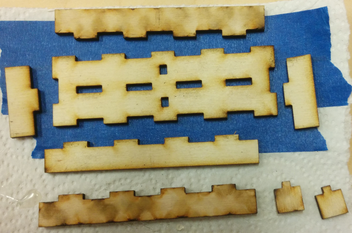
The individual parts of the case, as they are cut out
Pour a bunch of wood glue all over everything, and fit the pieces together. I also stuck the battery clips on while I was in a glue-ing state of mind:
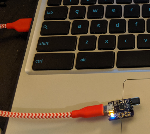
The parts all glued together
Once the glue dries, you can flatten the battery clips down and then solder the wires/tabs where appropriate. It might be a good idea to use a different sort of adhesive for the metal contacts, but this is just an example. Four AAA batteries in series will usually deliver between about 4.5-6 Volts, depending on the type of battery and how charged they are.
Conclusions
This script should scale well; you can also use it to generate patterns for larger items like a parts tray or jewelry box. You may need to separate the dividers into multiple cuts for larger boxes depending on how large your laser cutter is, but it is easy to re-arrange the parts with a program like Inkscape or Illustrator because the script places each divider in its own path within the SVG file.
Here is a Github repository with a working version of the script discussed in this post. And thanks to Seattle Makers for the laser cutter and expertise!
Cortez Goral
July 31, 2019 at 2:55 am
Hi everyone! I’m quite new to 3d printing and I have quite a few questions on the subject, so I hope you won’t get mad at me for asking here at least couple of them. I think before I’ll get seriously into sculpting I should focus on the software I’m going to use, and that’s what I would like to ask you about. Mainly, should I begin with the most simple/crudest program I can find or would it be better to start on something more complex? I’m worried that I’ll get some undesirable habits while working on less complex software. The second question is about the CAD software as well: should I look for CAD software that would let me design and slice it in it, or should I use a different software for each? Will it even make a difference? Weirdly, I couldn’t find the answer to that, as it seems like most articles want to focus on the very basics (like what is 3d printing and so on), and while the answers to those questions are fine, it seems like no one wants to go into the details (it looks like some of them even plagiarise each other! I swear I’ve found the same answers to the same questions on at least 3 different blogs) but I’m getting off-topic… The last question is about 3d pens. Would it be possible to somehow convert whatever I draw with a 3d pen to a 3d model in a program? For example, if I’ll draw a horse with 3d pen, would it be possible to get its design in a program? I’m not sure how that could even work, but the very idea sounds interesting to me. Anyway, I think I’ll stop here just in case no one will answer me and all of this writing will be for nothing. I’m sorry that I’m using your content to ask questions, but I hope you’ll understand and advice a beginner like me. Anyway, thank you for posting. I learned something from this and that’s always appreciated. Thank you, and I hope to hear back from you very soon 🙂
Vivonomicon
August 22, 2019 at 10:37 am
Good luck with your projects, but I think that your questions are a little bit beyond the scope of my knowledge. I’m sorry that I don’t know very much about 3D printing, but for sculpting, it seems like you might be better served by subtractive manufacturing. From what I remember, 3D-printed parts usually require a lot of polishing and ‘post-processing’ to look nice, and it’s hard to make stable parts with 3D pens because the layers don’t usually fuse too well together. Maybe the pens have gotten better in recent years, though, and they look like a fun way to ‘doodle’ outside of CAD programs.
Good luck, and sorry again for my lack of knowledge. There are a lot of great resources for learning about 3D printing if you search, and those places will have much better information than I do.