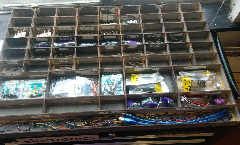
Lately, I’ve been looking for ways to get people interested in basic electronics, and things like kits and/or lessons seem like a great way to do that. I’ve also been looking for ways to learn about making things with a laser cutter, so I decided to put together a stack-able box that could double as storage and a display for available electronics parts at a local makerspace.
The basic idea was simple; start with a box ‘outline’ similar to those generated by Makercase, and then lay out a grid pattern of ‘dotted lines’ to slot crenellated dividers into. I wanted something like a shallow tray, with several horizontal and vertical dividers to hold different types of parts. What could possibly go wrong?
At this point, with a basic idea and maybe a quick sketch, most sane people would open up a program like Autodesk Inventor, Solidworks, or Adobe Illustrator. Options like Inkscape, OpenSCAD, or SolveSpace would also work well if you like free software. But after having some trouble with SVG exports, I wondered if it might make sense to just write the files by hand, for a simple grid pattern.
I guess it depends on your definition of ‘sense’! In this post, we’ll learn how to write SVG files for a small laser-cut ‘test’ box:
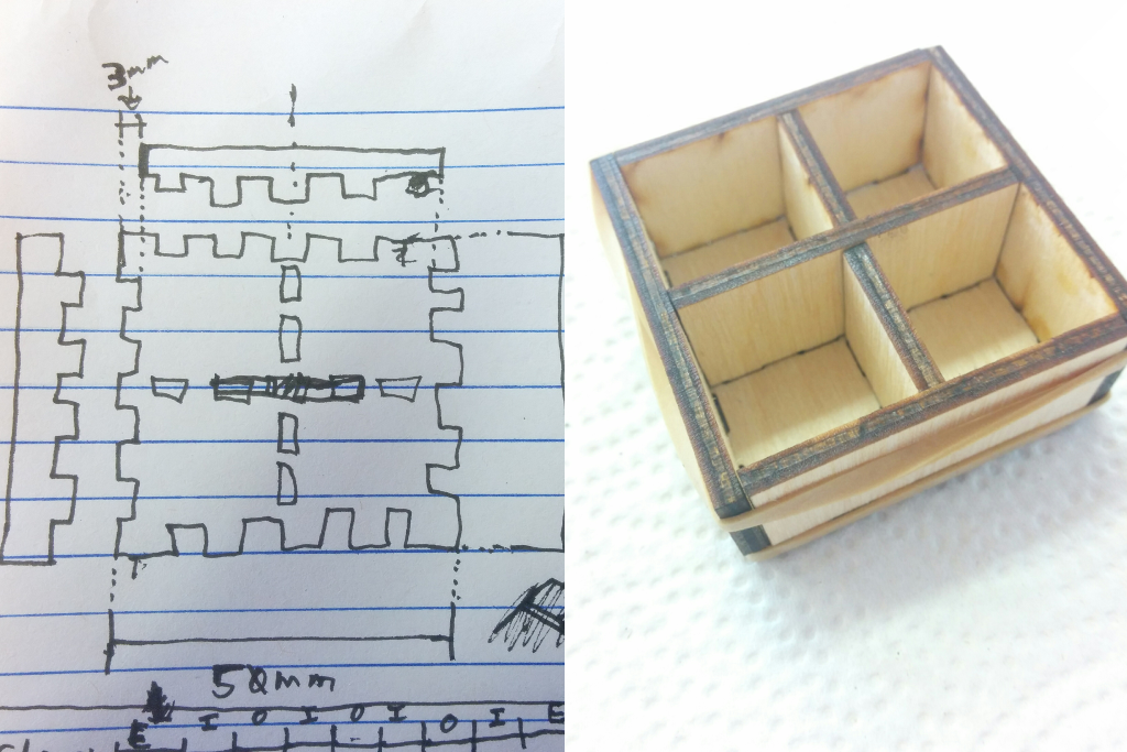
Quick sketch of a test box, and what it’ll look like.
SVG: ‘Scalable Vector Graphics’
I should start this section with a huge thanks to Joni Trythall’s Pocket Guide to Writing SVG ebook – it looks like this was a Kickstarter’d project which got open sourced after reaching its funding goals. Doesn’t that just give you the warm fuzzies? It’s a well-written introduction to the basics of the SVG file format, and it is where I learned just about everything that I’m about to try to explain.
So it turns out that the SVG format is very similar to how HTML is structured. If you’ve never seen HTML files before, I would recommend taking a quick look at a page like W3Schools’ “HTML Basics” to get a basic idea of the “nested tag” structure that these documents use.
A tag in an SVG file is a lot like a tag in an HTML file – it defines either something to draw, or some properties to apply to other tags. A ‘rect’ tag draws a rectangle, a ‘circle’ tag draws a circle, and so on. A tag’s properties define things like where to draw the shape, how large it should be, and what color to use.
It’s tempting to use simple ‘rectangle’ shapes for something like a box, but in our illustration above, the box’s base looks more like a jigsaw puzzle piece. For that sort of shape, it’s better to use a ‘path’. A path is a series of lines and curves which define the outline of a shape, and we define them by moving an imaginary paintbrush around an imaginary canvas. You can read more about them in the Pocket Guide linked above, but here is a quick example path and a description of each command in its ‘d’ (‘data’) string on a 100-square-pixel canvas:

<path d="M10,10 h80 L10,90 v-80 Z" />
- “M10,10”: “Move the paintbrush to coordinates (10, 10).”
- “h80”: “Drag the paintbrush 80 units horizontally to the right.”
- “L10,90”: “Drag the paintbrush in a line to coordinates (10, 90).”
- “v-80”: “Drag the paintbrush 80 units vertically up.”
- “Z”: “We are done; complete the path.”
Following those steps, our imaginary paintbrush will draw the triangle shown above with points at (10, 10), (90, 10), and (10, 90), where (0, 0) is the top-left of the image and (100, 100) is the bottom-right. It doesn’t look like a paintbrush drew an outline along our path, but that is because the SVG default is to fill shapes with black and not draw any outline. We can set the ‘stroke‘ and ‘fill‘ properties on our tag to change those colors. For example, we can fill the shape with pink and draw a green outline:
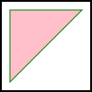
<path stroke="green" fill="pink" d="M10,10 h80 L10,90 v-80 Z" />
You can also replace the “green”/”pink” color strings with a custom hexadecimal color using the format, “#RRGGBB”. The laser cutter doesn’t care what color our lines are, but I will be using ‘fill=”none”‘ for these test patterns so that only outlines are drawn. The only other option we might need is, ‘stroke-linejoin=”miter”‘, which ensures that the corners of our paths will be rectangular instead of rounded. You can also change the width of a path with a property like, ‘stroke-width=”0.1″‘.
Setting our Scale
The real-world units used by SVG files are arbitrary until we specifically define a reference scale. But the ‘S’ in ‘SVG’ stands for ‘Scalable’, so that’s an easy thing to do. In the outermost ‘svg’ tag, we can simply define ‘width’, ‘height’, and ‘viewBox’ properties. The ‘width/height’ values define how large the image is, and the ‘viewBox’ value defines our system of coordinates using X/Y/Width/Height. We can use units including pixels (‘px’), inches (‘in’), and millimeters (‘mm’). As an example, here is the same design written as two different SVG files:

<svg width="100px" height="100px" viewBox="0 0 100 100" xmlns="http://www.w3.org/2000/svg" >
  <path d="M50,20 L80,80 L20,80 L50,20 Z" />
</svg>
<svg width="100px" height="100px" viewBox="0 0 1 1" xmlns="http://www.w3.org/2000/svg">
  <path d="M0.5,0.2 L0.8,0.8 L0.2,0.8 L0.5,0.2 Z" />
</svg>
In the ‘viewBox’ definition, the first two (X, Y) numbers represent the upper-left corner of the viewport and the second two (W, H) numbers represent its width/height. These two files describe the same image; the units are a bit different, but the triangle always has its points at (50px, 20px), (80px, 80px), and (20px, 80px). In the first file, the coordinates are given in their raw pixel values because the ‘viewBox’ width/height values match the image’s width/height pixel values. In the second file, the coordinates are all based on a ‘unit’ scale, as fractional values between 0 and 1.
A Test Box
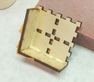
So, let’s try cutting out a small test box, to make sure this all actually works. It will consist of a base, four walls, and some ‘wells’ divided by a single horizontal wall and two smaller vertical ones – here’s how it wound up turning out, so you can get an idea of how the outline of each part will fit into the box:
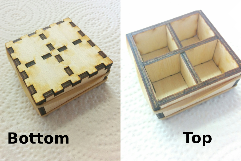
How the test box fits together.
I used some scrap 3mm-thick plywood and randomly chose a 50mm-square box with walls and dividers that are 20mm tall. Why not? Each compartment winds up being a little over 20x20mm on the inside. Using what we’ve learned about writing SVG files so far, (and a calculator) we should be able to create files for all of the necessary parts. A 50mm box with four ‘notches’ per side makes each ‘notch’ one ninth of the total, or roughly 5.55mm long.
So, here is an image of the box’s base, and the contents of its ‘.svg’ file as raw text. The outline is just a single path with a series of horizontal and vertical lines, and several rectangles in a ‘+’ pattern outline the slots which the dividers will fit into:

<svg width="50mm" height="50mm" viewBox="0 0 50 50" xmlns="http://www.w3.org/2000/svg">
  <g id="outlines" fill="none" stroke="black"
     stroke-width="0.1mm" stroke-linejoin="miter">
    <!-- Box base outline -->
    <path d="M0,0
             h5.54 v3 h5.56 v-3 h5.56 v3 h5.56 v-3
             h5.56 v3 h5.56 v-3 h5.56 v3 h5.56 v-3 h5.54
             v5.54 h-3 v5.56 h3 v5.56 h-3 v5.56 h3
             v5.56 h-3 v5.56 h3 v5.56 h-3 v5.56 h3 v5.54
             h-5.54 v-3 h-5.56 v3 h-5.56 v-3 h-5.56 v3
             h-5.56 v-3 h-5.56 v3 h-5.56 v-3 h-5.56 v3 h-5.54
             v-5.54 h3 v-5.56 h-3 v-5.56 h3 v-5.56 h-3
             v-5.56 h3 v-5.56 h-3 v-5.56 h3 v-5.56 h-3 v-5.54
             L0,0 Z" />
    <!-- Horizontal divider notches. -->
    <rect x="5.54" y="23.5" width="5.56" height="3" />
    <rect x="16.66" y="23.5" width="5.56" height="3" />
    <rect x="27.78" y="23.5" width="5.56" height="3" />
    <rect x="38.9" y="23.5" width="5.56" height="3" />
    <!-- Vertical divider notches. -->
    <rect x="23.5" y="5.54" width="3" height="5.56" />
    <rect x="23.5" y="16.66" width="3" height="5.56" />
    <rect x="23.5" y="27.78" width="3" height="5.56" />
    <rect x="23.5" y="38.9" width="3" height="5.56" />
  </g>
</svg>
The ‘g’ tag in that SVG file defines a ‘group’ of objects which will share the ‘g’ tag’s properties. You can read more about that in the Pocket Guide linked earlier. Here, it is only used to give the path and rectangles the same style. Moving on, here are the left/right walls, which are just a single path:

<svg width="23mm" height="50mm" viewBox="0 0 23 50" xmlns="http://www.w3.org/2000/svg">
  <path fill="none" stroke="black" stroke-width="0.1mm" stroke-linejoin="miter"
        d="M0,0 h20
           v5.54 h3 v5.56 h-3 v5.56 h3 v5.56 h-3
           v5.54 h3 v5.56 h-3 v5.56 h3 v5.56 h-3 v5.56
           h-20 v-50 L0,0 Z" />
</svg>
The top/bottom walls, which double as the single horizontal divider:

<svg width="44mm" height="23mm" viewBox="0 0 44 23" xmlns="http://www.w3.org/2000/svg">
  <path fill="none" stroke="black" stroke-width="0.1mm" stroke-linejoin="miter"
        d="M0,0 h44 v20
           h-2.54 v3 h-5.56 v-3 h-5.56 v3 h-5.56 v-3
           h-5.56 v3 h-5.56 v-3 h-5.56 v3 h-5.56 v-3 h-2.54
           v-20 L0,0 Z" />
</svg>
And finally, the little vertical dividers:

<svg width="23mm" height="20.5mm" viewBox="0 0 23 20.5" xmlns="http://www.w3.org/2000/svg">
  <path fill="none" stroke="black" stroke-width="0.1mm" stroke-linejoin="miter"
        d="M0,0 h20
           v2.54 h3 v5.56 h-3 v5.56 h3 v5.56 h-3 v1.28
           h-20 v-20.5 L0,0 Z" />
</svg>
We can open each of those files in a program like Inkscape, which seemed happy with them and can export the .DXF format which seems to be common for laser cutters, as well as .PNG files for people like me who haven’t worked out SVG support on their blog yet. I won’t go into the details on how to use Inkscape, since there are already much better tutorials on the subject, you probably already have your own workflow for SVG files, and ‘File -> Save as…’ usually works fine anyways.
Assembly
So here’s what the laser cuts out:
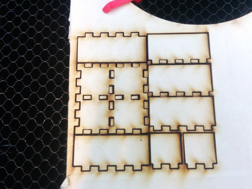
The basic process I use is to attach the walls first, then fit the dividers in while trying to keep everything level and square. I used ordinary wood glue, which seems to work well if you take some care to keep the dividers at right angles to the base. When assembling a larger box, I did have some of the longer dividers bow upwards a bit, so laying something heavy along their length or clamping them down is probably a good idea while the glue is still drying.
Anyways, waxy masking tape (and/or maybe painter’s tape?) doesn’t seem to stick to wood glue, which makes it very useful for holding parts together while the glue dries:
Masking tapes around the corners hold the box’s shape while it dries.
Masking tape’s waxiness also means that to attach the dividers you can simply layer some tape over the bottom of the box’s base, fill the holes with wood glue, and then insert the dividers into the glue-filled wells. Horsehair brushes work well for cleaning up the glue that seeps out of the holes, and for getting glue up into the box’s vertical gaps.
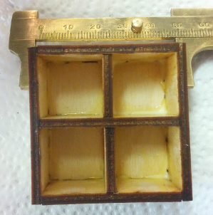
Once the glue dries, you can remove the masking tape. You might also have to let the newly-exposed faces sit a little longer, to give any glue which was stuck under the tape and not exposed to air time to dry out. But there we go, one hand-written 50x50mm box!
Conclusions
Okay, fine, writing out SVG files is not going to be a good solution for large-scale projects. There don’t seem to be any good options for defining variables or parameters, which makes it difficult to create designs which can be modified later.
But it was a fun exercise and it wound up working reasonably well. Plus, it’s interesting to see how simple the .SVG format can be. I’d like to follow up on this post with a modular script to generate patterns for these sorts of ‘grid’ display/storage boxes, but that might take a little while to get around to.
Also, thanks to Seattle Makers for the laser cutter and expertise! Here’s how the parts box turned out, before attaching an acrylic cover to the hinges – it could have stained better, but at least everything fit and the result is sturdy: