
FPGA
Learning FPGA Design with nMigen
Like many of us, I’ve been stuck indoors without much to do for the past month or so. Unfortunately, I’m also in the process of moving, so I don’t know anyone in the local area and most of my ‘maker’ equipment is in storage. But there’s not much point in sulking for N months straight, so I’ve been looking at this as an opportunity to learn about designing and implementing FPGA circuits.
I tried getting into Verilog a little while ago, but that didn’t go too well. I did manage to write a simple WS2812B “NeoPixel” driver, but it was clunky and I got bored soon after. In my defense, Verilog and VHDL are not exactly user-friendly or easy to learn. They can do amazing things in the hands of people who know how to use them, but they also have a steep learning curve.
Luckily for us novices, open-source FPGA development tools have advanced in leaps and bounds over the past few years. The yosys and nextpnr projects have provided free and (mostly) vendor-agnostic tools to build designs for real hardware. And a handful of high-level code generators have also emerged to do the heavy lifting of generating Verilog or VHDL code from more user-friendly languages. Examples of those include the SpinalHDL Scala libraries, and the nMigen Python libraries which I’ll be talking about in this post.
I’ve been using nMigen to write a simple RISC-V microcontroller over the past couple of months, mostly as a learning exercise. But I also like the idea of using an open-source MCU for smaller projects where I would currently use something like an STM32 or MSP430. And most importantly, I really want some dedicated peripherals for driving cheap addressable “NeoPixel” LEDs; I’m tired of needing to mis-use a SPI peripheral or write carefully-timed assembly code which cannot run while interrupts are active.
But that will have to wait for a follow-up post; for now, I’m going to talk about some simpler tasks to introduce nMigen. In this post, we will learn how to read “program data” from the SPI Flash chip on an iCE40 FPGA board, and how to use that data to light up the on-board LEDs in programmable patterns.

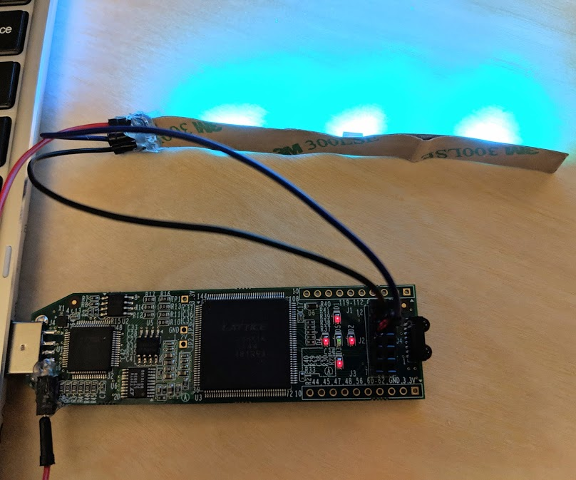
The LEDs on these boards are very bright, because you’re supposed to use PWM to drive them.
The target hardware will be an iCE40UP5K-SG48 chip, but nMigen is cross-platform so it should be easy to adapt this code for other FPGAs. If you want to follow along, you can find a 48-pin iCE40UP5K on an $8-20 “Upduino” board or a $50 Lattice evaluation board. If you get an “Upduino”, be careful not to mis-configure the SPI Flash pins; theoretically, you could effectively brick the board if you made it impossible to communicate with the Flash chip. The Lattice evaluation board has jumpers which you could unplug to recover if that happens, but I don’t think that the code presented here should cause those sorts of problems. I haven’t managed to brick anything yet, knock on wood…
Be aware that the Upduino v1 board is cheaper because it does not include the FT2232 USB/SPI chip which the toolchain expects to communicate with, so if you decide to use that option, you’ll need to know how to manually write a binary file to SPI Flash in lieu of the iceprog commands listed later in this post.
Learning how to FPGA with ‘Neopixel’ LEDs
Whenever I talk to someone about FPGAs, the conversation seems to follow a familiar routine. It is almost a catechism to say that ‘FPGAs are very interesting niche products that, sadly, rarely make sense in real-world applications’. I often hear that organizations with Money can afford to develop ASICs, while hobbyists are usually better served by today’s affordable and powerful microcontrollers except in some very specific circumstances like emulating old CPU architectures. I don’t have enough experience to know how accurate this is, but I do have a couple of projects that seem like they could benefit from an FPGA, so I decided to bite the bullet and learn the basics of how to use one.
I chose a popular $25 development board called the ‘Icestick‘ to start with. It uses one of Lattice’s iCE40 chips, which is nice because there is an open-source toolchain called Icestorm available for building Verilog or VHDL code into an iCE40 bitstream. Most FPGA vendors (including Lattice) don’t provide a toolchain that you can build from source, but thanks to the hard work of Clifford Wolf and the other Icestorm contributors, I can’t use “maddeningly proprietary tools” as a reason not to learn about this anymore.
One thing that FPGAs can do much better than microcontrollers is running a lot of similar state machines in parallel. I’d eventually like to make a ‘video wall’ project using individually-addressable LEDs, but the common ‘Neopixel’ variants share a maximum data rate of about 800kbps. That’s probably too slow to send video to a display one pixel at a time, but it might be fast enough to send a few hundred ‘blocks’ of pixel data in parallel. As a small step towards that goal, I decided to try lighting up a single strip of WS2812B or SK6812 LEDs using Verilog. Here, I will try to describe what I learned.
Blue Icestick
And while this post will walk through a working design, I’m sorry that it will not be a great tutorial on writing Verilog or VHDL; I will try to gloss over what I don’t understand, so I would encourage you to read a more comprehensive tutorial on the subject like Al Williams’ series of Verilog and Icestorm tutorials on Hackaday. Sorry about that, but I’m still learning and I don’t want to present misleading information. This tutorial’s code is available on Github as usual, but caveat emptor.